

下载

Maxim > Design Support > Technical Documents > Application Notes > Microprocessor Supervisor Circuits > APP 4839
Keywords: microprocessor supervisors, power sequencers
APPLICATION NOTE 4839
Supervise and Power-Sequence a SoC
By: Eric Schlaepfer, Applications Engineer
Feb 10, 2011
Abstract: Microprocessors, microcontrollers, and system-on-chip devices (SoCs) that operate with
multiple supply voltages often require a reset pulse to initialize properly, and the supply voltages must
turn on in a specific sequence to prevent damage via unexpected current paths. Sequencing for two
voltages can be implemented with just a pair of microprocessor-supervisor ICs (MAX6418).
A similar version of this article appeared in the May 13, 2010 issue of EDN magazine.
Microprocessors, microcontrollers, and systems on chip (SoCs) often need a reset pulse to initialize
properly. Many of these devices also use separate I/O and core voltage supplies. When multiple supplies
are used, the supplies must be turned on in a specific sequence to prevent the circuits from ending up in
an unknown state or burning out due to unexpected current paths. The voltages should also be
monitored to ensure that the device will not come out of reset until both voltages settle to levels within
the operating voltage range.
A previous design idea¹ presents a circuit performing the reset function. Unfortunately this circuit suffers
from a number of limitations. The circuit does not monitor the voltage on the 3.3V rail, the 1.8V rail
suffers from poor monitoring accuracy since the 3.3V rail is used as a reference, the reset delay may not
be present if the power rails are sequenced in the reverse order, the reset pulse has a glitch that could
cause problems with the SoC, and the reset delay capacitor may not be reset correctly if power is rapidly
cycled.
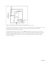
The inexpensive circuit in Figure 1 uses a MAX6418 to provide a glitch-free reset pulse with a well-
defined pulse width to accurately monitor both the 3.3V and the 1.8V rails. Resistors R1 and R2 can be
adjusted to set the monitoring threshold for different core voltages according to the following formula:
V
TH
= 1.263(1 + R1/R2). Adjust C1 for different pulse widths. Calculate C1 using this formula: C1 = (t -
275e
-6
)/(2.73e
6
), where t is the desired delay in seconds and C1 is in Farads.
Page 1 of 4