
下载

Maxim > Design Support > Technical Documents > Application Notes > A/D and D/A Conversion/Sampling Circuits > APP 1811
Maxim > Design Support > Technical Documents > Application Notes > Amplifier and Comparator Circuits > APP 1811
Maxim > Design Support > Technical Documents > Application Notes > Optoelectronics > APP 1811
Keywords: modulated laser, diode driver, visible-light laser, optical, photodiode, photo diode, peak optical
power, visible laser driver
APPLICATION NOTE 1811
Visible-Laser Driver Has Digitally Controlled Power
Modulation
Jul 01, 2001
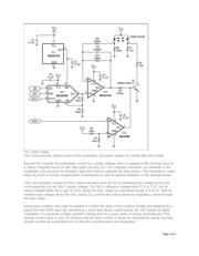
Abstract: The circuit in the figure below includes a 10-bit digital-to-analog converter (DAC) with 3-wire
serial input that operates and maintains a visible-light laser diode at constant average optical output
power. A separate digital input line (MOD) enables a comparator with open-drain output (IC4) to
implement digital communications by pulsing the laser-diode through Q1.
Many laser diodes include a photodiode that generates a current proportional to the intensity (optical
power) of the laser beam. Most of these photodiodes, however, have relatively slow response times and
cannot track the peak optical power of a typical modulated laser diode. Instead, the driver circuits for
these devices control the laser by monitoring a relative average optical power.
The circuit in the figure below includes a 10-bit digital-to-analog converter (DAC) with 3-wire serial input
that operates and maintains a visible-light laser diode at constant average optical output power. A
separate digital input line (MOD) enables a comparator with open-drain output (IC4) to implement digital
communications by pulsing the laser-diode through Q1. Circuit components were chosen to minimize the
layout are and cost.
Page 1 of 3