


下载
Maxim > Design Support > Technical Documents > Application Notes > Digital Potentiometers > APP 3846
Keywords: Wien bridge, digital potentiometer, digital pot, oscillator, JFET, variable resistor
APPLICATION NOTE 3846
Analysis of a Digitally Controlled Wien-Bridge
Oscillator
May 24, 2006
Abstract: Of all the low-frequency oscillator configurations, the Wien bridge is the easiest to use. It is
reliable, uses standard components, gives a good sine wave, and is fairly immune to the type of op amp
around which it is designed. A Wien bridge can, however, be misunderstood and oversimplified, leading
to designer frustration. This article describes the theory and practicalities of using a Wien-bridge
oscillator, and how to make the circuit more stable and more factory-/user-flexible.
The Wien-Bridge Oscillator Circuit
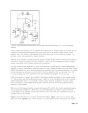
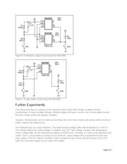
The circuit of a standard Wien-bridge oscillator is shown in Figure 1.
Figure 1. A standard Wien-bridge oscillator circuit.
A circuit maintains oscillation when the loop gain at the frequency of oscillation is unity, and the phase
shift of the feedback signal at the frequency of oscillation is zero or a multiple of 2 π.
First, the phase shift needs to be considered. In Figure 1, R1 and C1 produce a positive phase-shifted
current with respect to the output voltage. When this phase-shifted current meets R2 and C2, these latter
components produce a negative phase-shifted voltage. At a specific frequency, the phase shift caused
by R1 and C1 is offset by an equal and opposite phase shift caused by R2 and C2, so the net phase
Page 1 of 7