
下载

Maxim > Design Support > Technical Documents > Application Notes > Temperature Sensors and Thermal Management > APP 3457
Keywords: Temperature sensor, IR, isolation, transmitter, receiver
APPLICATION NOTE 3457
IR-Link Temperature Sensor Allows Isolation of the
Temp Sensor
Mar 14, 2005
Abstract: A circuit is described that transmits temperature data over an IR link, thus allowing isolation of the
temperature sensor. The circuit consists of an IR transmitter, an IR receiver, and a temperature sensor.
The problem of obtaining temperature readings from points at potentials a few tens of volts from ground is
difficult, and as the voltage difference grows it becomes harder. The same is true for high-EMI environments.
A temperature probe linked only by an IR connection to the readout point could be a good solution for those
cases. The problem of powering such a sensor can be simplified by a design that minimizes power
consumption, and by using a long shelf life, high-energy-density battery (lithium primary cell).
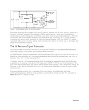
The IR-Linked Sensor/Transmitter
The MAX6576 is a low-power (140µA), internal sensor, temperature-to-period converter IC. It comes in a 6-
pin SOT package, can read temperatures between -40°C and +125°C, and operates from a supply between
2.7V and 5.5V. Its output is a square wave with a period proportional to the absolute temperature (K) of the IC
die temperature. The proportionality factor can be set (hardwired) as 10, 40, 160, or 640ms/K (1K = -
273.15°C). In this application, it is set at the lowest operating frequency (highest averaging, lowest noise),
resulting in a period of 192ms (about 5.2Hz) at room temperature (+25°C = 298K). This period is faster than
the time constant of the MAX6576 itself, which is the maximum temperature slew rate that the unit can sense.
At +125°C, (max operating temperature), the signal period is 255ms; at -40°C (min), it is 149ms.
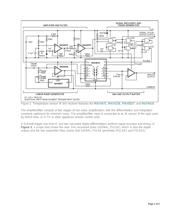
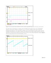
Each positive-going transition of the square-wave output from the MAX6576 triggers the IR transmitter circuit
of Figure 1 to generate a short (about 10µs), high-intensity IR pulse. The circuit is very simple: one fourth of a
74HC132 quad dual-input Schmidt trigger IC is used as a positive edge differentiator, while the remaining
three gates are paralleled and used as the IR LED driver. The IR LED is a standard type, used for handheld
remote-control units. The total consumption measured in the prototype unit when measuring near room
temperatures is less than 140µA.
Page 1 of 5