
下载

Maxim > Design Support > Technical Documents > Application Notes > Amplifier and Comparator Circuits > APP 3520
Maxim > Design Support > Technical Documents > Application Notes > Filter Circuits (Analog) > APP 3520
Maxim > Design Support > Technical Documents > Application Notes > Video Circuits > APP 3520
Keywords: HDTV, reconstuction filter, single supply amplifier
APPLICATION NOTE 3520
Low-Cost, 30MHz, Triple-Channel HDTV
Reconstruction Filter
By: Marvin Li
Jun 20, 2005
Abstract: This application note describes how to use the MAX4382 triple amplifier to construct a low-
cost, triple-channel, three-pole, lowpass Sallen-Key filter with a dual supply voltage. The circuit provides
a Butterworth response with a 30MHz bandwidth, and is ideal for video-reconstruction filtering in HDTV
applications. The MAX4382 is also shown as part of a single-supply, input-bias network with the same
filter performance as the dual-supply configuration.
In HDTV applications, lowpass filters are used for reconstruction of RGB and component video (Y, Pb,
and Pr) signals. They are placed following the video DAC to remove the higher frequency replicas of the
signals, as well as before the ADC for anti-aliasing. The MAX4382 high-speed, triple-channel amplifier
can be used to build such lowpass filters that are ideal for HDTV applications.
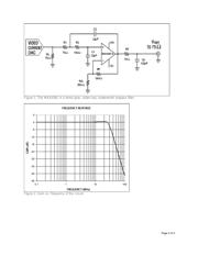
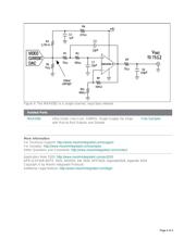
Figure 1 shows a one-channel, dual-supply configuration incorporating the MAX4382. It is a three-pole,
Sallen-Key Butterworth lowpass filter, in which the current DAC generates the video signal, and the
resistor (RL) sets the amplitude. With the MAX4382, the RL, R1, R2, C1, and C2 form a two-pole,
Sallen-Key lowpass filter having a gain of 2. The driving load (75Ω) at the output, plus RT and Cp, sets
the real pole. In the Figure 1 circuit, the -3dB bandwidth is about 30MHz (Figure 2). The attenuation is
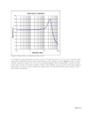
approximately 14dB at 44.25MHz, and 28dB at 74.25MHz. The group delay is roughly 6.5ns (Figure 3).
If the current DAC load is different than 75Ω, just use the following relationship to set the value of R1:
R1 + RL = 150Ω. For RL greater than 150Ω, C1, C2, R1, and R2 will need to be adjusted.
Page 1 of 4