

下载

Maxim > Design Support > Technical Documents > Application Notes > Amplifier and Comparator Circuits > APP 3390
Maxim > Design Support > Technical Documents > Application Notes > Video Circuits > APP 3390
Keywords: termination, resistor termination, driving 75Ω, minimize reflections, op amps, line driver, cable
matching, characteristic impedance matching, video
APPLICATION NOTE 3390
Reduced Termination Loss by Active Synthesis of
Output Impedance
Dec 21, 2004
Abstract: In high-speed transmission-line applications, it is important to match the output impedance of a
line driver to the line. While this is achieved usually with a resistor, an active impedance synthesis has
advantages. This application note describes how to use positive feedback around an op amp to create
the desired output impedance. Equations and circuit examples are given for low-noise audio, and video
op amps driving 50Ω to 600Ω loads.
The Need for Termination
The output impedance of a circuit is important in transmission line-driving applications. The transmission
line impedance, which is determined by the physical geometry of the conductors and insulation, must be
matched at both the send and receive ends in order to minimize degrading signal reflections. When the
characteristic impedance is not correctly matched at the drive and the receiver ends, not all of the signal
energy is delivered to the load. Some energy is reflected back and will distort (or sometimes, almost
cancel) the forward signal to the load.
RF engineers require accurate 50Ω terminations for their coaxial cables, video transmission engineers
require accurate 75Ω terminations for their cables, and broadcast engineers require accurate 600Ω
terminations for their audio circuits. Other standard termination values are 110Ω, 120Ω and 500Ω. The
termination requirements are not confined to analog signals. Digital signals depend on correct line
termination for accurate, high-speed transmission throughout a system.
Passive Resistive Termination
The usual method for achieving termination is to use a buffer amplifier with low output impedance, and
add series resistance to the required value. This approach is simple, provided that the preceding buffer
amplifier truly has a low output impedance across the band of interest.
A serious disadvantage of the simple resistor approach is, however, the 6dB loss of signal between the
buffer output and the terminated load. This results in a serious loss of signal headroom, particularly in
single supply systems.
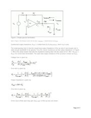
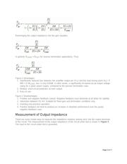
Figure 1 shows a closed-loop buffer amplifier with a series resistance added outside the feedback loop
to set the output impedance when measured looking back into the amplifier load terminal.
Page 1 of 11