
下载
Maxim > Design Support > Technical Documents > Application Notes > Amplifier and Comparator Circuits > APP 3201
Maxim > Design Support > Technical Documents > Application Notes > Automotive > APP 3201
Keywords: pulse-width modulation, PWM, pulse width modulator, integrator, comparator, triangle-wave
generator
APPLICATION NOTE 3201
Pulse-Width Modulator Operates at Various Levels
of Frequency and Power
Jun 23, 2004
Abstract: Build a general-purpose pulse-width modulator using three op amps from a quad-op-amp
device.
The many applications for pulse-width modulation (PWM) include voltage regulation, power-level control,
and fan-speed control. A PWM circuit for such applications (Figure 1) can be implemented with three op
amps from a single quad-op-amp chip. The use of op amps allows a wide variety of applications. Low-
power op amps can be used in a low-power system, for example, and high-frequency op amps can be
used for a high-frequency PWM. The Figure 1 circuit also generates a triangular wave.
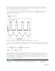
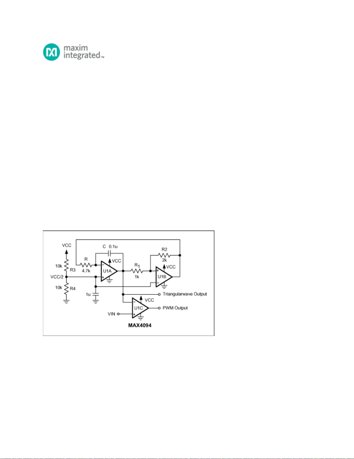
Figure 1. This 3-op-amp circuit produces a triangular wave and a variable-pulsewidth output.
The circuit consists of a triangle-wave generator (U1A and U1B) and a comparator (U1C). U1A is
configured as an integrator (or de-integrator), and U1B as a comparator with hysteresis. At power-up,
the comparator's output voltage is assumed to be zero.
U1A's non-inverting input is biased at VCC/2. A virtual connection between the inverting and non-
inverting inputs allows a constant current through R equal to I = VCC/2R, which charges the capacitor C.
Thus, the U1A integrator output increases linearly with time. When it reaches 0.75VCC, the comparator
output (U1B) changes to its maximum output voltage (VCC). At that point the integrator begins to de-
Page 1 of 3