
下载

Maxim > Design Support > Technical Documents > Application Notes > Microcontrollers > APP 2391
Keywords: dual voltage tracking, MAX5039, MAX5040, voltage tracking controller, PowerPC, ASIC, DSP,
core, I/O, voltage tracking, dsp core voltages, microprocessor voltages, tracking voltage
APPLICATION NOTE 2391
Dual Voltage Tracking Circuit for I/O,
Microprocessor, and DSP Core Voltages
Sep 29, 2003
Abstract: This note describes a dual tracking controller for a single I/O voltage and two core voltages. It
describes how to apply the circuit to one or many core voltages.
Principles covered include: the need for tracking, practical circuits, controller functions, selection of
tracking voltage levels, component value selection, overall circuit accuracy, circuit stability, the
characteristics of some commercially-available DC/DC converters, and cascaded supply and parallel
supply operation. Circuits are provided with options and tracking waveforms. A component-selection
spreadsheet for calculating component values (Excel, 196KB) is available
Voltage Tracking Requirements
It is important that a microprocessor's input/output (I/O) and core voltages not depart from a
manufacturer's specifications at power-up and power-down. A typical contemporary microprocessor's I/O
section usually operates at 3.3V or 2.5V, while the core may operate at 1.8V, 1.5V or 1.3V. Typical
requirements are that the core and I/O voltages not differ from one another more than a small specified
amount during power up/down, and that the voltages not be out of tolerance longer than a few tens of
milliseconds during power up or power down. Guidelines on the PowerPC™, for example place a 20ms
limit on out-of-tolerance I/O and core voltages at power up/down and a ±50mV spec on core voltage.
The latter spec, incidentally, suggests better than ±2.8% supply accuracy (including any series tracking-
circuit voltage drop) at 1.8V.
Voltage Tracking Methods
Several methods are in use to satisfy the power-up/down tracking requirements: Schottky-diode matrix
circuits, multi-channel series tracking circuits, and shunt tracking circuits. While series tracking exhibits
series voltage/power loss, diode matrices require complex diode selection and a diode can blow under
short circuit conditions, shunt tracking has neither drawback. The MAX5039 and MAX5040 shunt tracking
controllers not only eliminate series voltage/power loss but minimize tracking-circuit component count to
contribute to a lowest-cost solution. Only one MOSFET is required (per core voltage) to effect tracking of
I/O and core voltages, and this MOSFET is active for only a few milliseconds during power-up/down.
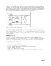
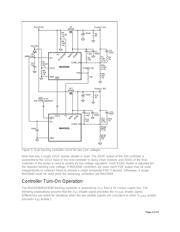
Basic Circuit Description
The basic dual shunt voltage-tracking controller circuit of Figure 1 employs a single MAX5039 tracking
Page 1 of 23