

下载
Keywords:
RTD, resistance temperature detector, temperature measurement, high accuracy, MAXREFDES67, universal input
APPLICATION NOTE 6262
RTD MEASUREMENT SYSTEM DESIGN ESSENTIALS
Abstract: This application note describes the methods to minimize error in RTD temperature measurement.
Introduction
High-accuracy temperature measurements provide essential data for industrial automation applications to ensure both product quality and safety. Many types of
temperature sensors are available, and each one has its advantages and disadvantages. This application note focuses on resistance temperature detectors (RTD), and
explains the design essentials to optimize the measurement accuracy.
Resistance Temperature Detectors
RTDs contains an element whose resistance changes with temperature. Most elements are either platinum, nickel, or copper. A platinum RTD provides the best
performance because platinum has the most linear and repeatable temperature-to-resistance relationship over a large temperature range.
Generally, RTDs generate more stable and repeatable outputs, compared to thermocouples and thermistors. Hence, RTDs achieve higher measurement accuracy.
High-Accuracy RTD Measurement Design Options
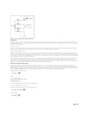
The two most common methods to measure an RTD are constant current excitation (
Figure 1) and constant voltage excitation (Figure 2).
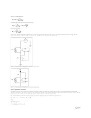
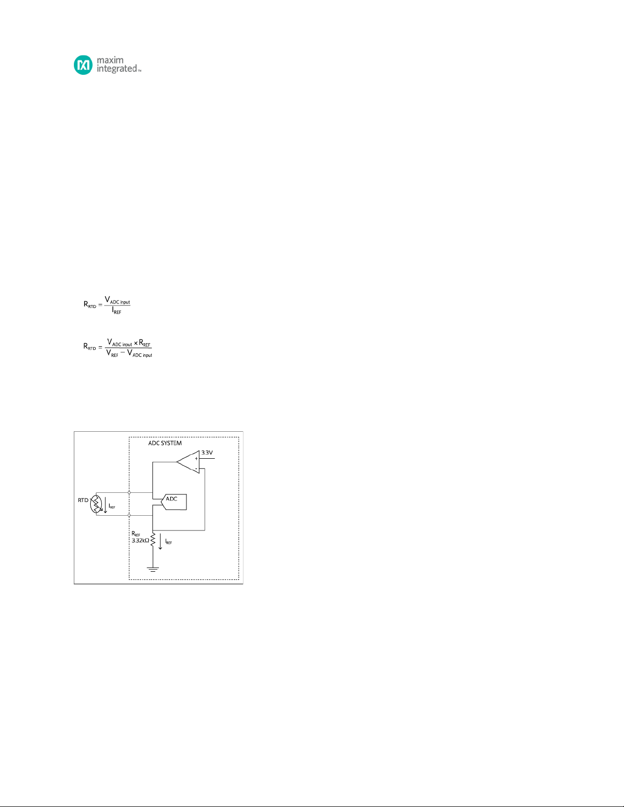
The goal is to accurately measure the RTD resistance and convert it to temperature using an equation or a lookup table. For ideal cases:
for constant current excitation,
or
for constant voltage excitation.
However in practice, the lead wires of the RTD have resistance. Long lead wires greatly affect the measurement accuracy. Therefore, the actual resistance measured by
the circuits shown in Figures 1 and 2 is:
RTD + (2 × R
),
where R
is the resistance of the lead wires, assuming both wires have the same resistance. Although theoretically acceptable, the same R implies that both
wires are of the exact same length and made with the exact same material. Such an assumption cannot be guaranteed in critical temperature sensing applications. For
this reason, RTDs feature 3-, and 4-wire configurations to help eliminate the measurement error contributed by lead wires.
Figure 1. 2-wire constant current excitation configuration.
WIRE
WIRE WIRE
Page 1 of 8