
下载

Keywords:
power regulator control, pulse-frequency modulation, PFM, pulse-width modulation, PWM, hysteretic control, constant on-time
control , COT
APPLICATION NOTE 5999
CHOOSE THE RIGHT REGULATOR FOR THE JOB: PART 2,
PRIMARY REGULATOR CONTROL SCHEMES
By:
Don Corey, Principal Member of Technical Staff, Maxim Integrated
Abstract: This application note is Part 2 of a 3-part series on power regulators and discusses primary regulator control schemes: pulse-
frequency modulation (PFM), hysteretic, and constant on-time topologies (COT). A short discussion follows about secondary control such
as skip mode.
Overview
Part 1:
Brief review of the importance of duty cycle and load usage. The main focus is regulator control schemes, their types, critical
parameters, and compensation schemes. We will finish with a short description of internal versus external FET's.
Part 2: Other topologies besides voltage mode (VM) and current mode (CM) control that incorporate constant on-time, hysteretic, and
pulse-frequency modulation (PFM) topologies. Also explains how to select these regulator types for an application.
Part 3:
closes with how to select and simulate the optimal regulator for an application.
Introduction
One size does not fit all! Quite the opposite. Semiconductor companies target segment markets and tailor regulator parameters to the end-
product requirements. Clearly, understanding the application will help dictate the right choice of regulator.
In
Choose the Right Regulator for the Job: Part 1 , we discussed two regulator control schemes, current mode (CM) and voltage mode
(VM), for pulse-width modulated (PWM) converters. We also examined the critical differences between those control modes. In that
application note, we explained how the product application is very important for selecting the right regulator.
In Part 2 we examine other commonly used regulator control topologies and describe the application benefits for each. Besides the VM
and CM PWM control, modern regulators incorporate other primary control schemes: pulse-frequency modulation (PFM), hysteretic, and
constant on-time topologies (COT). After we look at each, we add a short discussion about secondary control methods, such as skip mode.
Later,
Part 3 provides basic equations to help a designer choose the best regulator for an application and optimize the surrounding
components.
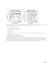
A PFM Converter Provides Better Overall Efficiency
A PFM converter
is an alternative DC-DC architecture. This control scheme varies the converter switching frequency in direct relationship
to the converter load. Consequently, the architecture is referred to as PFM. Many portable applications will use PFM mode to maximize
battery life, because a PFM converter is much more efficient at light loads than a PWM-based converter.
Electromagnetic interference (EMI) is an important consideration when choosing between a PWM or PFM converter. In PWM mode, the
switching frequency is fixed so EMI from converter switching is predicable and constant, and in many cases can be filtered. Many PWM
converters also offer external, frequency synchronization input to help mitigate conflict with other important signal frequencies often present
on the application board. If an application requires more than one voltage, all the switching converters can be clocked at the same
frequency. This approach eliminates the inherent beat frequencies when multiple converters are not switching at the same frequency and
not perfectly phase aligned. In contrast to PWM topologies, the switching frequency is variable for PFM, and it is much harder to control
EMI. As such, PFM mode may not be the best choice for powering sensitive audio or RF low-noise circuits. PFM would, however, be an
excellent choice when efficiency must be optimized over a wide range of output loads.
It should be noted, finally, that many converters have provisions to run in either PFM or PWM mode. A logic-controlled mode pin or internal
circuitry automatically switches between these two modes based on load current.
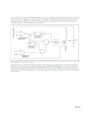
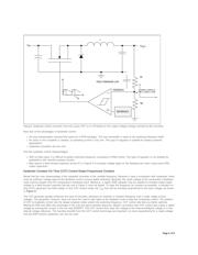
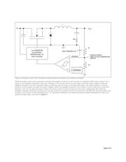
Operation of a PFM Controller
In step-up PFM control
two one-shot circuits operate based on the load current from the DC-DC converter's output. The PFM is based on
two switching times (the maximum on-time and the minimum off-time) and two control loops (a voltage-regulation loop and a maximum
peak-current, off-time loop). The PFM is also characterized by control pulses of variable frequency. The two one-shot circuits in the
controller define the T
(maximum on-time) and the T (minimum off-time). The T one-shot circuit activates the second one-shot,
1
1
ON OFF on
Page 1 of 8