


下载

Maxim > Design Support > Technical Documents > Application Notes > Automotive > APP 5571
Maxim > Design Support > Technical Documents > Application Notes > LED Lighting > APP 5571
Keywords: LED driver, boost converter, high brightness, step-by-step, design, debug, test, spreadsheet,
calculator
APPLICATION NOTE 5571
Step-by-Step Design Process for the MAX16833
High-Voltage High-Brightness LED Driver, Part 1
By: Greg Fattig
Mar 01, 2013
Abstract: This application note details a step-by-step design process for the MAX16833 high-voltage
high-brightness LED driver. This process can speed up prototyping and increase the chance for first-
pass success. A typical design scenario is presented, along with example calculations based on the
design constraints. Component selection trade-offs are discussed. A spreadsheet calculator is included to
help calculate external component values. This application note focuses on the boost converter topology.
However, the same process can be applied to other topologies as long as the underlying equations are
understood. For a buck-boost converter design example, see application note 5659, “Step-by-Step
Design Process for the MAX16833 High-Voltage High-Brightness LED Driver, Part 2.”
Introduction
This application note is the first in a series that details a step-by-step design process for the MAX16833
high-voltage high-brightness LED driver to speed up prototyping and increase the chance for first-pass
success. The MAX16833 is a peak current-mode-controlled LED driver, capable of driving an LED string
in several different architectures: boost, buck-boost, SEPIC, flyback, and high-side buck topologies. The
second application note in the series, application note 5659, “Step-by-Step Design Process for the
MAX16833 High-Voltage High-Brightness LED Driver, Part 2,” focuses on the buck-boost converter
topology. This application note, Part 1, focuses on the boost topology.
The MAX16833 offers several features: a dimming driver designed to drive an external p-channel
MOSFET, extremely fast PWM current switching to the LEDs without transient overvoltage or
undervoltage, analog dimming, programmable switching frequency between 100kHz and 1MHz, and the
option of either a ramp output for frequency dithering or a voltage reference for precisely setting the LED
current with few external components.
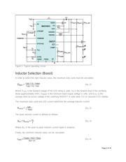
For the design example here in Part 1, a 7 LED string is driven with a constant current of 1A. Assume
that each LED has a typical forward voltage drop of 3V and a dynamic resistance of 0.2Ω. Also assume
that the LED driver circuit is running directly off of the car battery, which has a typical voltage of 12V but
can vary from 6V to 16V. Since the LED string voltage is always greater than the input voltage, the boost
configuration is chosen.
Page 1 of 16