
下载

Maxim > Design Support > Technical Documents > Application Notes > Power-Supply Circuits > APP 280
Keywords: Power Supplies for Telecom Systems
APPLICATION NOTE 280
Power Supplies for Telecom Systems
Jul 17, 2002
Ever-higher levels of integration offered by new semiconductor technology are enabling today's telecom
systems to incorporate more and more functions in increasingly smaller dimensions. Smaller-geometry
processes ensure less power consumption, lower working voltages, and fewer square mils of silicon per
function. New PC boards often include ICs operating at 5V, 3.3V, 2.5V, O.8V, and so on.
Power requirements for ICs of this new generation are more stringent in terms of load, line, and static
voltage regulation. In some cases (those governed by the Intel VRM 8.2 specification, for instance), the
output voltage is programmed by means of a digital bus for levels between 1.8V and 3.5V with load
currents of 30A or more. Power-supply technology in general has not kept up with this trend, although
semiconductor technology allows a higher integration, complete automatic board assembly, and a smaller
pitch between the boards.
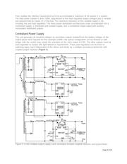
Except in rare cases, power supplies cannot be assembled automatically. Most have big heatsinks for
thermal management that compel a manual assembly. For the majority of telecom systems, conventional
cooling techniques have forced a growth in the heatsink dimensions. The heatsink surface that is
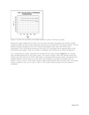
required relates directly to the power-supply efficiency (Figure 1). Thus, the new power-supply voltages
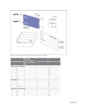
(3V and lower) have a direct influence on heatsink dimensions. Consider a forward converter, as
illustrated in Figure 1, operating at 100W:
With 5V output: P
LOSS
= 100(P
OUT
/eff.) - P
OUT
= 100(100/83) - 100 = 20.5W
With 3V output: P
LOSS
= 100(100/70) - 100 = 42.9W
Page 1 of 14