

下载

Maxim > Design Support > Technical Documents > Application Notes > Sensors > APP 753
Keywords: single pin, serial, communications, communication, asynchronous, MAX1452, serial data
APPLICATION NOTE 753
MAX1452 Serial Communications
Jul 22, 2002
Abstract: The MAX1452 utilizes asynchronous serial data communication via a single-pin interface. This
application note provides a detailed description of the serial communication system used and should be
read in conjunction with the MAX1452 data sheet.
This application note describes the serial communications system used in the MAX1452, and it is best
read in conjunction with the MAX1452 data sheet. It expands on the serial communications information
contained in the data sheet and provides communication examples.
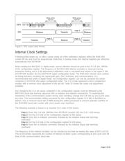
MAX1452 Digital Mode
The MAX1452 digital input/output (DIO) provides single-pin serial communications with internal control
functions and memory. All command inputs flow into a set of 16 registers, which form the interface
register set (IRS). Additional levels of command processing are provided by control logic, which takes its
inputs from the IRS. A bidirectional 16-bit latch buffers data to and from the 16-bit calibration registers
and internal (8-bit-wide) EEPROM locations. Figure 3 shows the relationship between the various serial
commands and the MAX1452's internal architecture.
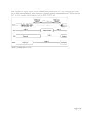
Communication Protocol
The DIO serial interface is used for asynchronous serial data communications between the MAX1452
and a host calibration test system or computer. The MAX1452 automatically detects the baud rate of the
host computer when the host transmits the initialization sequence. Baud rates between 4800 and 38,400
can be detected and used. The data format is always 1 start bit, 8 data bits, and 1 stop bit. The 8 data
bits are transmitted LSB first, MSB last. A weak pullup can be used to maintain a logic 1 on DIO while
the MAX1452 is in digital mode. This is to prevent unintended 1 to 0 transitions on this pin, which would
be interpreted as a communication start bit. Communications are allowed only when the Secure-Lock™
byte is disabled (i.e., CL[7:0] = 00
HEX
) or UNLOCK is held high.
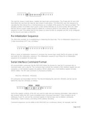
Initialization Sequence
The first command byte sent to the MAX1452 after power-up or following receipt of the re-initialization
command is used by the MAX1452 to learn the communication baud rate. The initialization sequence is
a 1-byte transmission of 81 hex, as follows:
Page 1 of 16