
下载

Maxim > Design Support > Technical Documents > Application Notes > A/D and D/A Conversion/Sampling Circuits > APP 3418
Maxim > Design Support > Technical Documents > Application Notes > Measurement Circuits > APP 3418
Maxim > Design Support > Technical Documents > Application Notes > Sensors > APP 3418
Keywords: Sigma Delta, Digital Filter, Lowpass Filter, SINC Filter, SINC, 50Hz Rejection, 60Hz Rejection,
50/60Hz Rejection, Simultaneous 50/60Hz Rejection, Normal Mode Rejection
APPLICATION NOTE 3418
Understanding the Effects of Clock Tolerances on
50/60Hz Noise Rejection in High Performance
Sigma Delta ADCs
Dec 17, 2004
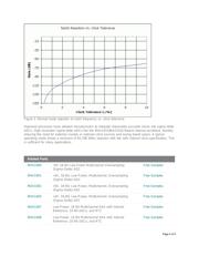
Abstract: This article explores the effect of clock tolerance on the performance of the lowpass decimation
and digital filter inherent in sigma-delta ADCs, and especially the filter notch frequencies. Low-bandwidth
sigma-delta applications commonly take advantage of the digital filter to provide 50Hz, 60Hz, or
simultaneous 50Hz/60Hz noise rejection. It is important to understand the relationship between clock
frequency and filter characteristics of the digital filter when choosing an external clock crystal or selecting
an internal clock.
Sigma-delta ADCs use a modulator to convert an analog input to a series of impulses. The ratio of 1's to
0's on the modulator output represents the average value of the analog input. The output of the modulator
goes to a digital filter. Common implementations of the digital filter in sigma-delta ADCs are a lowpass
filter with a SINC (Sin(x)/x) impulse response. The filter's output goes to a decimator to reduce the data
rate of the output data.
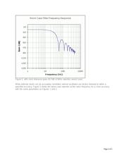
Besides the obvious function of filtering the quantization noise, the SINC filter has the added benefit of
providing filter notches at integer multiples of the data output rate. For example, a 60Hz data output rate
will have notches at 60Hz, 120Hz, 180Hz, etc. By strategically tuning filter notches at frequencies of
known noise sources, (i.e., 50Hz or 60Hz powerline noise), substantial noise rejection can be realized.
This is useful when using high-resolution sigma-delta ADCs to measure low bandwidth, low-level signals
in the presence of 50Hz/60Hz noise.
The output data rate and frequency of the filter notches are functions of the modulator frequency,
decimation ratio, and filter order. The decimation ratio is the ratio of the modulator frequency and the
output data rate. The modulator frequency is a function of the ADC clock frequency.
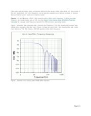
The SINC filter, which is typically 3
rd
order and denoted SINC³, is defined in the frequency domain as:
H(f) = [1/N * Sin(N*π*f/f
M
) / Sin(π*f/f
M
)]³
Where: N is the decimation ratio
f
M
is the modulator frequency
Page 1 of 5