
下载
Keywords:
4-20mA current control loop, PLC, PIXI, ADCs, DACs, Current sense amplifiers.
APPLICATION NOTE 6221
PIXI MAX11300 4-20MA CURRENT CONTROL LOOP TRANSMITTER
By:
Tom Au-Yeung, Director of Customer Applications
Abstract: This application note reviews the operation of the 4–20mA current control loop transmission standard, and the application of the MAX11300 20-Port
Programmable Mixed-Signal I/O with 12-Bit Analog to Digital Converter (ADC), 12-Bit Digital to Analog Converter (DAC), Analog Switches, and GPIO to
measure -40°C to +70°C temperature range with less than 0.6% accuracy as the preferred choice of the transmitter.
Introduction
Temperature is one of the most widely measured parameters in industrial process control and automation, and 4–20mA current control loop is perhaps the most
common analog transmission standard used in industry for transmitting the data from remote sensors to a programmable logic controller (PLC) in a central
control center over a twisted-pair cable. This application note reviews the operation of this transmission standard, its advantages, and the application of the
MAX11300
20-Port Programmable Mixed-Signal I/O with 12-Bit Analog-to-Digital Converter (ADC), 12-Bit Digital-to-Analog Converter (DAC), Analog Switches,
and GPIO to measure -40°C to +70°C temperature range with less than 0.6% accuracy as the preferred choice of the transmitter in this 4–20mA control loop.
Detailed Description
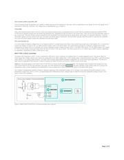
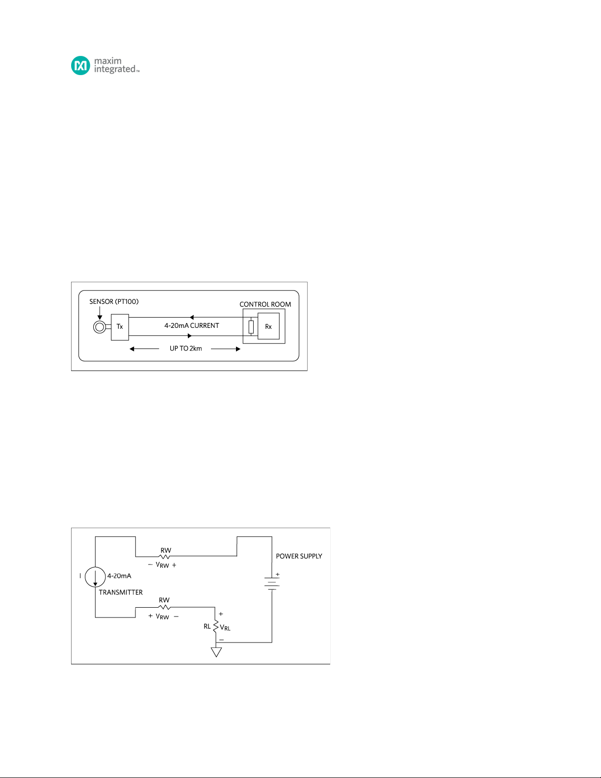
In two-wire 4–20mA control loops, the transmitters are typically used to convert various process signals such as flow, temperature, pressure, etc., to 4–20mA DC
current for transmitting the signal over a long distance up to 2km with little or no loss of signal as shown in
Figure 1.
Figure 1. Block Diagram of a typical 4–20mA current control loop.
In Figure 1, current supplied from the power supply flows through the wire to the 4–20mA transmitter, which is not only the source of current, but also regulates
the flow and magnitude of the current through the control loop. The current allowed by the transmitter is called the loop current which is proportional to the
parameter that is being measured. The loop current flows back to the controller through the electrical wire, then flows through the receiver resistor to ground and
returns to the power supply. The current flowing through receiver produces a voltage that is easily measured by an analog input of a controller or monitoring
device such as the MAX11300. For a 250Ω-resistor load as used in this demo board, the voltage is 1VDC at 4mA and 5VDC when the current in the loop is
20mA. 4mA current minimum is chosen so that when 0mA current is measured, it means the control loop is broken, alerting the controller of a potential problem.
The advantages of the 4–20mA current control loop are that the accuracy of the signal is not affected by the voltage drop in the loop since, unlike voltage,
current remains constant through an electrical conductor as long as the power-supply voltage is greater than the total voltage drop in the loop and that the
current is immune to noise.
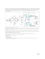
Power Supply:
For 4–20mA current control loops with 2-wire transmitters, common power supply voltages are 12, 15, 24, and 36 VDC. Power supplies for 2-wire transmitters
must always be DC voltage because the magnitude of the current flow represents the signal level that is being transmitted. If AC voltage were used in the loop,
the magnitude of current would be continuously changing, making it difficult to distinguish the signal levels being transmitted. The DC voltage must be set to a
level that is greater than the sum of the minimum voltage required to operate the Transmitter, the resistor load loss, V
, and for long transmission distances, the
V
drop in the wire as shown in the equivalent circuit in Figure 2.
Figure 2. 4–20mA current control loop equivalent circuit.
RL
RW
Page 1 of 8