
下载
Maximum Power
Enhancement Techniques
for Power Packages
Introduction
As packages become smaller, achieving efficient thermal
performance for power applications requires that the design-
ers employ new methods of meliorating the heat flow out of
devices. Thus the purpose of this paper is to aid the user in
maximizing the power handling capability of National Semi-
conductor’s power packages by using the SOT-223 as an
example. Ultimately the user may achieve improved compo-
nent performance and higher circuit board packing density
by using the thermal solution suggested below.
In natural cooling, the method of improving power perfor-
mance should be focused on the optimum design of copper
mounting pads. The design should take into consideration
the size of the copper and its placement on either or both of
the board surfaces. A copper mounting pad is important
because the substrate of the integrated circuit is mounted
directly onto the pad. The pad acts as a heatsink to reduce
thermal resistance and leads to improved power perfor-
mance.
Theory
When a device operates in a system under the steady-state
condition, the maximum power dissipation is determined by
the maximum junction temperature rating, the ambient tem-
perature, and junction-to-ambient thermal resistance.
P
DMAX
=(T
JMAX
−T
A
)/R
θJA
(1)
The term junction refers to the point of thermal reference of
the semiconductor. Equation (1) can also be applied to the
transient-state:
P
DMAX
(t)=[T
JMAX
−T
A
]/R
θJA
(t) (2)
where P
DMAX
(t) and R
θJA
(t) are time dependent. By using
the transient thermal resistance curves shown in the data
sheet, a transient temperature change can be calculated.
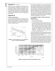
The transient thermal behavior is a complicated subject
because R
θJA
(t) increases non-linearly with time and the
conditions of the power pulse. A more thorough treatment of
transient power analysis is beyond the scope of this docu-
ment and the reader can refer to [13] for details.
R
θJA
has two distinct elements, R
θJC
junction-to-case and
R
CA
case-to-ambient thermal resistance.
R
θJA
=R
θJC
+R
θCA
(3)
The case thermal reference of the SOT-223 Power Package
is defined as the point of contact between the lead of the
package and the mounting surface.
R
θCA
is influenced by many variables such as ambient tem-
perature, board layout, and cooling method. Due to the lack
of an industry standard, the value of R
θCA
is not easily
defined and can affect R
θJA
significantly. In addition, the
case reference may be defined differently by various manu-
facturers. Under such conditions, it becomes difficult to de-
fine R
θCA
from the component manufacturer standpoint.
On the other hand, R
θJC
is independent of users’ conditions
and can be accurately measured by the component manu-
facturer.
Therefore, in this paper an effort has been made to define a
procedure which can be used to quantify the
junction-to-ambient thermal resistance R
θJA
which is more
useful to the circuit board designer.
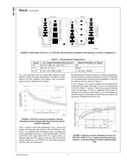
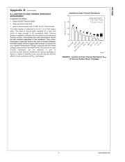
Result
The scope of the investigation has been limited to the size of
copper mounting pad and its relative surface placement on
the board. In still air with no heatsink, the application of these
heat dissipation methods is the most cost effective thermal
solution. A total of sixteen different combinations of 2 oz.
copper pad sizes and their placement were designed to
study their influence on R
θJA
thermal resistance. The con-
figurations of the board layout are shown in Figure 2 and
Table 1. Layouts 1 to 6 have the copper pad sizes from
0.0123 to 1 square inches on the top side of the board (top
side is defined as the component side of the board). Layouts
7 to 11 have copper pad sizes from 0.2 to 1 square inches on
the bottom side of the board. Layouts 12 to 16 have copper
pad sizes from 0.132 to 1 square inches divided equally on
both sides of the board.
20009401
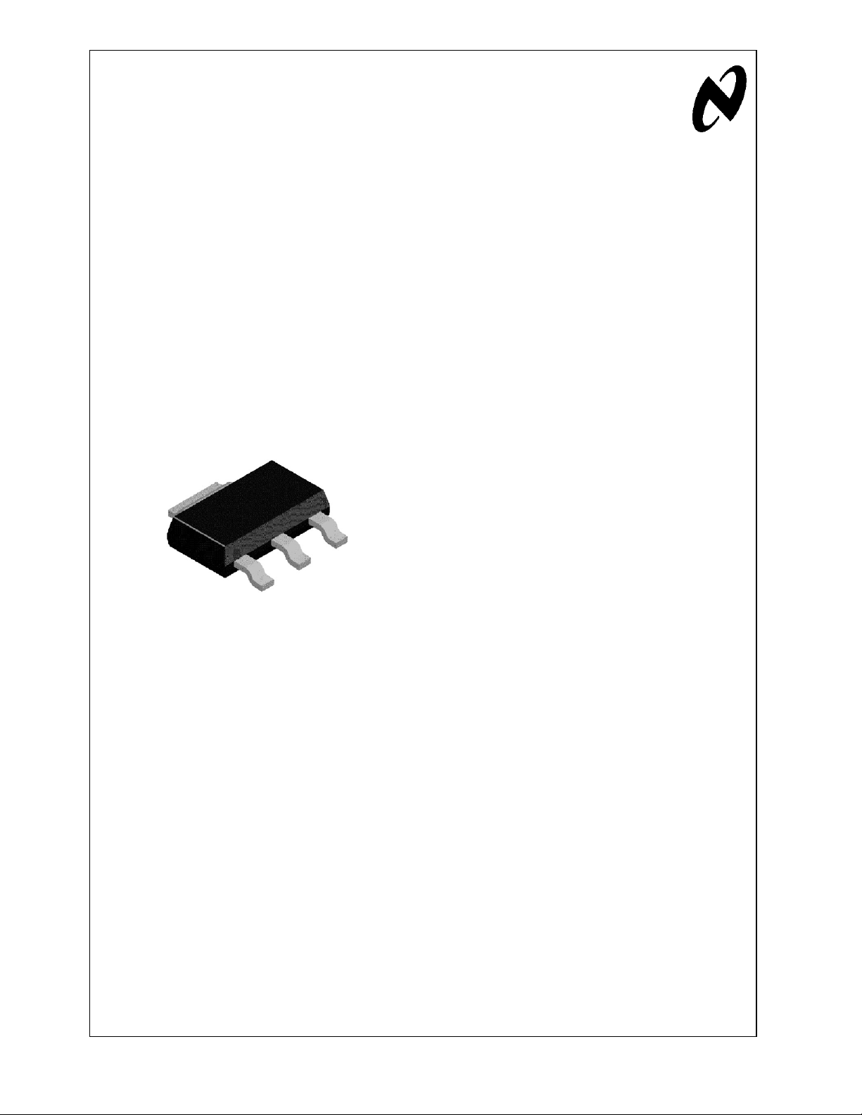
FIGURE 1. SOT-223 Package achieves junction-to-case
thermal resistance R
θJC
of 12˚C/W.
National Semiconductor
Application Note 1028
June 2001
Maximum Power Enhancement Techniques for Power Packages AN-1028
© 2002 National Semiconductor Corporation AN200094 www.national.com