
下载
Application Report
SNVA317A–April 2008–Revised April 2013
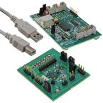
AN-1778 LM2755 Charge Pump LED Controller with I2C
Compatible Interface in µSMD
.....................................................................................................................................................
ABSTRACT
This application note discusses the LM2755 pump LED controller programmed via an I
2
C compatible
interface.
Contents
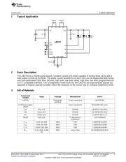
1 Typical Application .......................................................................................................... 3
2 Basic Description ............................................................................................................ 3
3 Bill of Materials .............................................................................................................. 3
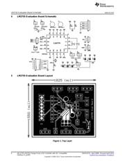
4 LM2755 Evaluation Board Schematic .................................................................................... 4
5 LM2755 Evaluation Board Layout ........................................................................................ 4
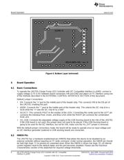
6 Board Operation ............................................................................................................. 6
6.1 Basic Connections ................................................................................................. 6
6.2 HWEN Pin .......................................................................................................... 6
6.3 SYNC Pin ........................................................................................................... 7
6.4 ADDR Pin ........................................................................................................... 7
6.5 External Control Interface Connection .......................................................................... 7
6.6 Operation Description ............................................................................................. 7
7 I
2
C Compatible Interface ................................................................................................. 8
7.1 Data Validity ........................................................................................................ 8
7.2 Start and Stop Conditions ......................................................................................... 9
7.3 Transferring Data .................................................................................................. 9
7.4 I
2
C Compatible Chip Address ................................................................................... 10
7.5 Internal Registers of LM2755 ................................................................................... 10
8 Software Interface Information ........................................................................................... 11
8.1 Example Diode Current Waveforms ........................................................................... 13
List of Figures
1 Top Layer .................................................................................................................... 4
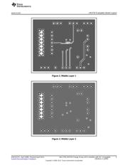
2 Middle Layer 1............................................................................................................... 5
3 Middle Layer 2............................................................................................................... 5
4 Bottom Layer (mirrored) ............................................................................................... 6
5 Data Validity Diagram ...................................................................................................... 8
6 Start and Stop Conditions.................................................................................................. 9
7 Write Cycle w = write (SDIO = "0") r = read (SDIO = "1") ack = acknowledge (SDIO pulled down by
either master or slave) rs = repeated start id = chip address, 18h if ADR = '0' or 67h if ADR = '1' for
LM2755....................................................................................................................... 9
8 Dimming Waveform ....................................................................................................... 10
9 GUI Start-Up ............................................................................................................... 11
10 Generic Read/Write Field................................................................................................. 11
11 Drop Down Menu.......................................................................................................... 11
All trademarks are the property of their respective owners.
1
SNVA317A–April 2008–Revised April 2013 AN-1778 LM2755 Charge Pump LED Controller with I2C Compatible
Interface in µSMD
Submit Documentation Feedback
Copyright © 2008–2013, Texas Instruments Incorporated