
下载

Application Report
SNVA022E–July 2000–Revised April 2013
AN-1157 Positive to Negative Buck-Boost Converter Using
LM267X SIMPLE SWITCHER
®
Regulators
.....................................................................................................................................................
ABSTRACT
The third generation Simple Switcher LM267X series of regulators are monolithic integrated circuits with
an internal MOSFET switch. These regulators are simple to use and require only a few external
components. In this article the design of a polarity inverting converter will be discussed.
Contents
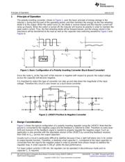
1 Principle of Operation ...................................................................................................... 2
2 Design Considerations ..................................................................................................... 2
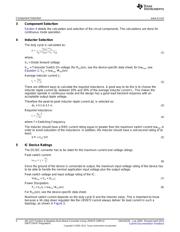
3 Component Selection ....................................................................................................... 4
4 Inductor Selection ........................................................................................................... 4
5 IC Device Ratings ........................................................................................................... 4
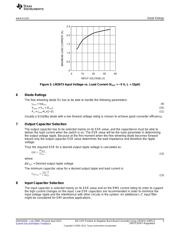
6 Diode Ratings ............................................................................................................... 5
7 Output Capacitor Selection ................................................................................................ 5
8 Input Capacitor Selection .................................................................................................. 5
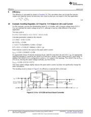
9 Efficiency ..................................................................................................................... 6
10 Example: Inverting Regulator, 12 V Input to −5 V Output at 1.5A Load Current ................................... 6
11 PCB Layout Guidelines .................................................................................................... 7
12 Stability Considerations .................................................................................................... 8
13 Startup Considerations ..................................................................................................... 8
List of Figures
1 Basic Configuration of a Polarity Inverting Converter (Buck-Boost Converter)..................................... 2
2 LM2673 Positive to Negative Converter ................................................................................. 2
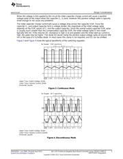
3 Continuous Mode ........................................................................................................... 3
4 Discontinuous Mode........................................................................................................ 3
5 LM2673 Input Voltage vs. Load Current (V
OUT
= −5 V, L = 33µH).................................................... 5
6 5 V to −15 V/150 mA Buck Boost Converter............................................................................ 6
7 Top Layer .................................................................................................................... 7
8 Silk Screen................................................................................................................... 7
9 LM2673 Demo Board 12 V to −5 V/1.5A (see for the Application Circuit) .......................................... 7
10 Load Transient Response Shows Stable Operation ................................................................... 8
SIMPLE SWITCHER is a registered trademark of Texas Instruments.
All other trademarks are the property of their respective owners.
1
SNVA022E–July 2000–Revised April 2013 AN-1157 Positive to Negative Buck-Boost Converter Using LM267X SIMPLE
SWITCHER
®
Regulators
Submit Documentation Feedback
Copyright © 2000–2013, Texas Instruments Incorporated