
下载
Application Report
SNOA930–March 2015
LDC Sensor Design
ChrisOberhauser
ABSTRACT
Getting the best performance out of an LDC requires a sensor suitable for the measurement. This app-
note covers the parameters to consider when designing a sensor for a specific application. Specific areas
of focus include the physical routing characteristics of PCB based sensors, considerations for the sensor
capacitor, and techniques to minimize or compensate for parasitic effects.
Contents
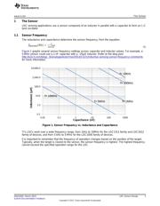
1 The Sensor ................................................................................................................... 3
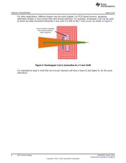
2 Inductor Characteristics..................................................................................................... 5
3 Capacitor Characteristics.................................................................................................. 19
4 Physical Coil Design....................................................................................................... 20
5 Summary .................................................................................................................... 23
6 References.................................................................................................................. 23
List of Figures
1 Sensor Frequency vs. Inductance and Capacitance.................................................................... 3
2 R
S
and R
P
.................................................................................................................... 4
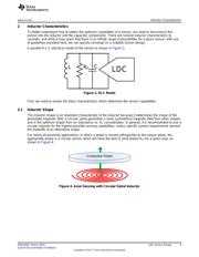
3 RLC Model.................................................................................................................... 5
4 Axial Sensing with Circular Spiral Inductor............................................................................... 5
5 Rectangular Coil is Insensitive to a Y-axis Shift ......................................................................... 6
6 Trapezoidal Inductor for Rotational Encoding............................................................................ 7
7 “Stretched” Rectangular Coil for lateral Position Measurement ....................................................... 8
8 Flat Circular Spiral Inductor ................................................................................................ 8
9 Inductance vs. Number of Turns for 18mm Circular Inductor.......................................................... 9
10 Multiple Layer Inductor Construction (Series) .......................................................................... 10
11 Simplified Electrical Model of 4 Layer Series Sensor (Ignoring R
P
) ................................................. 11
12 Mutual Inductance for 2 Layer Sensor (Ignoring R
P
) .................................................................. 11
13 Multi-layer Parallel Coil Schematic....................................................................................... 12
14 Multi-layer Parallel Inductor............................................................................................... 13
15 R
P
vs Normalized Target Distance....................................................................................... 14
16 Inductance vs. Normalized Target Distance............................................................................ 14
17 Sensor “Diameter” for a Non-circular Coil............................................................................... 15
18 Parasitic Capacitive Components in an Inductor....................................................................... 15
19 Inductance T vs. Frequency .............................................................................................. 16
20 Measurement of SRF with a VNA........................................................................................ 16
21 Wire Wound Inductor Parasitic Capacitance ........................................................................... 17
22 Winding-Out Method....................................................................................................... 17
23 Winding Crossing for Honeycomb Coil.................................................................................. 17
24 Combination of Both Winding-out and Crossing ....................................................................... 18
WEBENCH is a registered trademark of Texas Instruments.
All other trademarks are the property of their respective owners.
1
SNOA930–March 2015 LDC Sensor Design
Submit Documentation Feedback
Copyright © 2015, Texas Instruments Incorporated