
下载

1
SNOA945–February 2016
Submit Documentation Feedback
Copyright © 2016, Texas Instruments Incorporated
Optimizing L Measurement Resolution for the LDC1312 and LDC1314
All trademarks are the property of their respective owners.
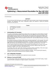
Application Report
SNOA945–February 2016
Optimizing L Measurement Resolution for the LDC1312
and LDC1314
ChrisOberhauser
ABSTRACT
TI’s LDC1312 and LDC1314 devices are versatile devices which provide 12 bits of inductive measurement
resolution. This application note covers configuration options and methods to improve the effective
resolution for these devices.
Contents
1 Understanding LDC Resolution............................................................................................ 1
2 LDC Configuration Parameters ............................................................................................ 1
3 LDC Clocking................................................................................................................. 4
4 Summary...................................................................................................................... 8
1 Understanding LDC Resolution
For an ADC, the resolution is generally the number of bits in the output word, and the effective resolution
is determined from the either the INL of static linearity or from the SINAD of a full scale sinewave. If the
signal amplitude input to an ADC is less than full scale, the resolution of the output word is still the same,
but the effective resolution decreases. For example, given an ADC with an input range of 1 VPP and an
effective resolution of 16 bits, if the input signal is only 500 mVPP, then the effective resolution will usually
be halved to 15 bits.
Most inductive sensors are not able to utilize the full scale input range that TI’s LDCs provide. This results
in a reduction in the effective resolution of the system. The larger the shift in sensor inductance due to
target movement, the more effective resolution the LDC can provide. A system which has an inductance
shift of 20% will have twice the effective resolution of an equivalent system which has a 10% shift.
TI’s LDC devices measure the inductance by measuring the resonant frequency of a sensor, and so the
LDC can be considered a frequency measurement version of an ADC. Where an ADC has an LSB
measured in voltage, an LDC has an LSB measured in Hz.
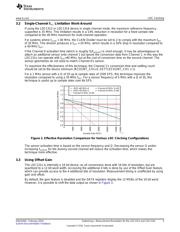
For example, with an LDC system with a frequency resolution of 50Hz (1LSB=50Hz), if the sensor signal
varies by 20 kHz, then the LDC would have an effective resolution of 8.6 bits.
There are two basic approaches to increase the effective resolution – first by improving the frequency
resolution, and second by increasing the sensor frequency variation.
2 LDC Configuration Parameters
There are several LDC parameters which determine the device resolution.
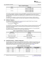
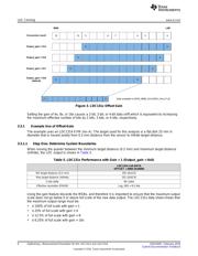
2.1 Reference Count and RCOUNT
The primary device setting which determines the conversion resolution is the RCOUNT setting. A higher
value for RCOUNT corresponds to a higher resolution L measurement.