


下载
© Semiconductor Components Industries, LLC, 2011
May, 2011 − Rev. 0
1 Publication Order Number:
AND9006/D
AND9006/D
Using Transmission Line
Pulse Measurements to
Understand Protection
Product Characteristics
Prepared by: Robert Ashton
ON Semiconductor
INTRODUCTION
Transmission Line Pulse (TLP) is a measurement
technique used in the Electrostatic Discharge (ESD) arena to
characterize performance attributes of devices under
stresses that have a short pulse width and fast rise time
similar to those of ESD events. TLP is applicable for both
system level ESD, as defined by IEC 61000−4−2, and
integrated circuit level HBM, as defined by
ANSI/ESDA/JEDEC JS−001−2010. One of TLP’s prime
uses is to obtain Current versus Voltage (I−V) data in which
each data point is obtained from a pulse that reflects the
characteristics of ESD waveforms: nanosecond rise times
and 100 ns pulse width. The 100 ns pulse length and current
levels up to 40 A used in TLP closely match the pulse lengths
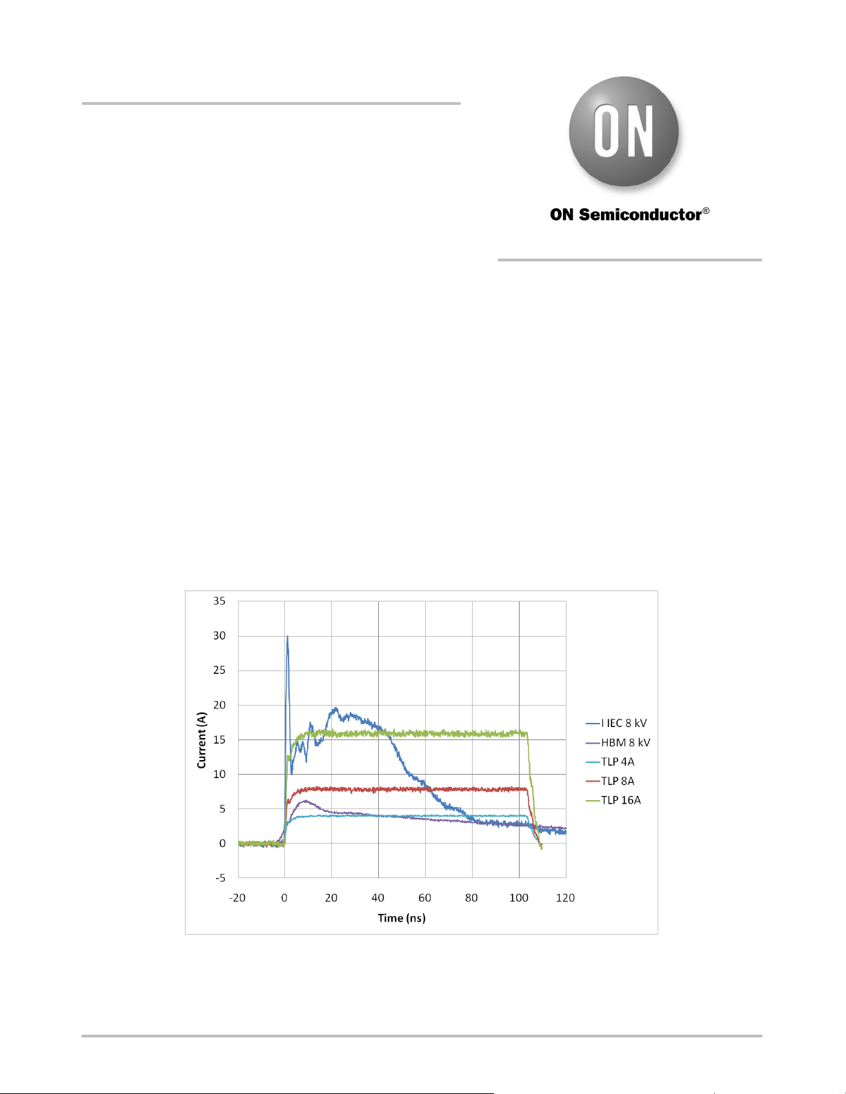
and currents that occur in ESD events. Figure 1 compares
IEC 61000−4−2 and Human Body Model (HBM) current
waveforms at 8 kV to TLP pulses at 8 A and 16 A. It is clear
that similarities in time scale and current level makes TLP
an ideal tool for characterizing the ESD properties of
electronic components. This Application Note will describe
the basic TLP measurements system, explain how I−V
curves are obtained using the TLP system and then show
some examples of how a TLP system can be used to
characterize ESD protection products such as
ON Semiconductors line of TVS devices.
Figure 1. Comparison of the Current Waveforms of IEC 61000−4−2 and HBM Waveforms with TLP Pulses at 4, 8
and 16 A
http://onsemi.com
APPLICATION NOTE