

© 2007 Microchip Technology Inc. DS01069B-page 1
AN1069
INTRODUCTION
The 25XXX series serial EEPROMs from Microchip
Technology are SPI compatible and have maximum
clock frequencies ranging from 3 MHz to 20 MHz. The
SPI module available on dsPIC33F Digital Signal
Controller and PIC24F microcontroller provide a very
easy-to-use interface for communicating with the
25XXX series devices. The largest benefit of using the
SPI module is that the signal timings are handled
through hardware rather than software. This allows the
firmware to continue executing while communication is
handled in the background. This also means that an
understanding of the timing specifications associated
with the SPI protocol is not required in order to use the
25XXX series devices in designs.
This application note is intended to serve as a
reference for communicating with Microchip’s 25XXX
series serial EEPROM devices with the use of the SPI
module featured on many dsPIC33F and PIC24F
family devices. Source code for common data transfer
modes is also provided.
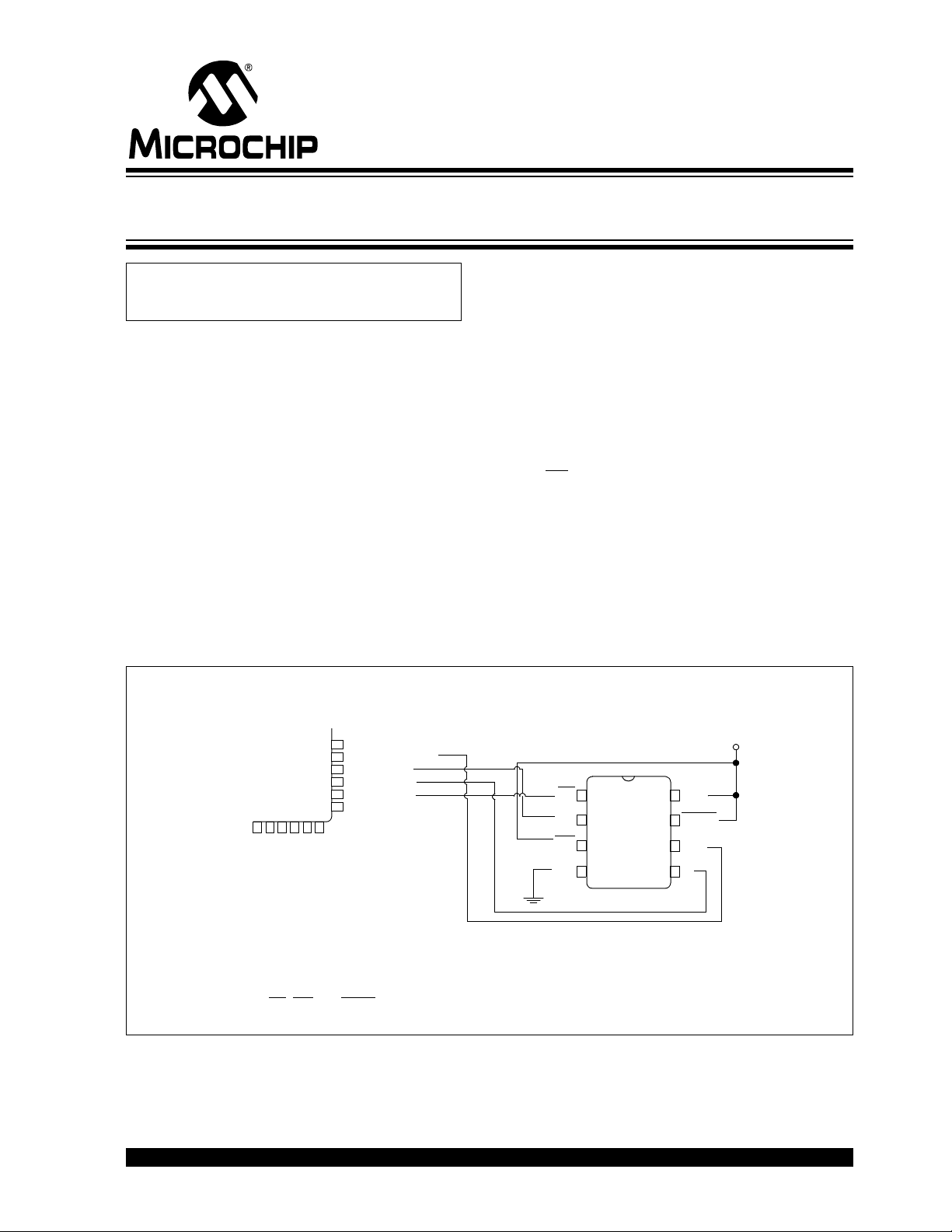
Figure 1 describes the hardware schematic for the
interface between Microchip’s 25XXX series devices
and the dsPIC33F DSC or the PIC24F MCU. The
schematic shows the connections necessary between
either controller and the serial EEPROM as tested, and
the software was written assuming these connections.
The WP
pin is tied to VCC because the STATUS regis-
ter write-protect feature is not used in the examples
provided.
FIGURE 1: CIRCUIT FOR dsPIC33FJ256GP710, PIC24FJ128GA010 AND 25XXX SERIES
DEVICE
Author: Martin Kvasnicka
Microchip Technology Inc.
CS
SO
WP
V
SS
V
CC
HOLD
SCK
SI
1
2
3
4
8
7
6
5
V
CC
25XXX
Note:
CS, WP and HOLD pins should all have pull-up resistors (~10k-ohms).
100 Pin TQFP
dsPIC33FJ256GP710
U1TX/RF3
U1RX/RF2
SDO1/RF8
SDI1/RF7
SCK1/INT0/RF6
SDA1/RG3
V
SS
V
DD
IC7/U1CTS/CN20/RD14
IC8/U1RTS/CN21/RD15
U2RX/CN17/RF4
U2TX/CN18/RF5
PIC24FJ128GA010
Using C30 Compiler and the SPI Module to Interface EEPROMs
with dsPIC33F and PIC24F