

下载

Maxim > Design Support > Technical Documents > Application Notes > Hot-Swap and Power Switching Circuits > APP 4883
Maxim > Design Support > Technical Documents > Application Notes > Miscellaneous Circuits > APP 4883
Maxim > Design Support > Technical Documents > Application Notes > Power-Supply Circuits > APP 4883
Keywords: oscilloscope, scope, measurement, hot-swap, hot-plug, load, switch, power, SOA, MOSFET
APPLICATION NOTE 4883
Oscilloscope Math Functions Aid Hot-Swap Circuit
Analysis
By: Dwight Larson, Senior Member of the Technical Staff
Nov 03, 2011
Abstract: Digital oscilloscopes are the norm in most engineering labs, but the chances are that you have
not fully explored their features. Among the more interesting features of a digital oscilloscope is the
"math" channel, which can be applied in novel ways to simplify and expand the analysis of hot-swap and
load-switching circuits. This application note shows how to connect the oscilloscope's probes to a hot-
swap circuit to obtain accurate values for MOSFET power dissipation and load capacitance. The
MAX5976 hot-swap solution serves as the example device.
A similar version of this article appeared in the October 1, 2011 issue of Test & Measurement World
magazine.
Introduction
Among the more interesting features of a digital oscilloscope is the "math" channel, which can be applied
in novel ways to simplify and expand the analysis of hot-swap and load-switching circuits. With clever
use, oscilloscope math functions enable the calculation of load capacitance or reveal the transient power
dissipation in a MOSFET during startup or shutdown. Math functions can yield detailed real-world
information about hot-swap circuit parameters that are otherwise subject to approximations and
estimates. Such information is invaluable, both for design and for troubleshooting of hot-swap and load-
switching circuits.
This application note shows how to connect the oscilloscope's probes to a hot-swap circuit to obtain
accurate values for MOSFET power dissipation and load capacitance.
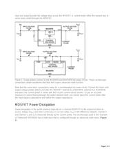
Oscilloscope Setup
For simplicity in this demonstration, we chose the MAX5976 hot-swap solution, which combines an
internal MOSFET switching element with the current-sensing and driver circuitry necessary to implement
a complete power-switching circuit. (The following test method also applies to hot-swap control circuits
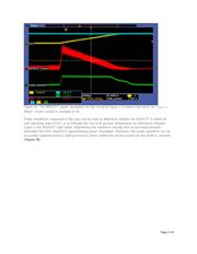
built from discrete components.) By connecting scope probes to the hot-swap circuit as shown in Figure
1, the oscilloscope can access the signals needed for calculations. Voltage probes connected to the
Page 1 of 8