


下载
March 2010 Doc ID 14763 Rev 2 1/39
AN2782
Application note
Solution for designing a 400 W fixed-off-time controlled
PFC preregulator with the L6562A
Introduction
In addition to the transition mode (TM) and fixed-frequency continuous conduction mode
(FF-CCM) operation of PFC pre-regulators, a third approach is proposed that couples the
simplicity and affordability of TM operation with the high-current capability of FF-CCM
operation. This solution is a peak current-mode control with fixed off-time (FOT). Design
equations are given and a practical design for a 400 W board is illustrated and evaluated.
Two methods of controlling power factor corrector (PFC) pre-regulators based on boost
topology are currently in use: the fixed-frequency (FF) PWM and the transition mode (TM)
PWM (fixed on-time, variable frequency). The first method employs average current-mode
control, a relatively complex technique requiring sophisticated controller ICs (e.g. the
L4981A/B from STMicroelectronics) and a considerable component count. The second one
uses the simpler peak current-mode control, which is implemented with cheaper controller
ICs (e.g. the L6561, L6562, L6562A from STMicroelectronics), much fewer external parts
and is therefore much less expensive. In the first method the boost inductor works in
continuous conduction mode (CCM), while TM makes the inductor work on the boundary
between continuous and discontinuous mode, by definition. For a given power throughput,
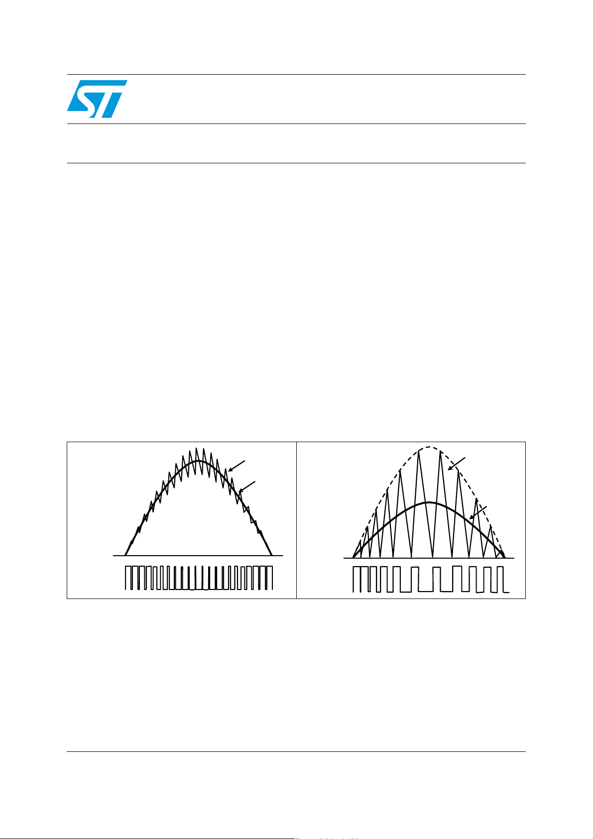
TM operation involves higher peak currents as compared to FF-CCM (Figure 1 and 2).
This demonstration, consistent with the above mentioned cost considerations, suggests the
use of TM in a lower power range, while FF-CCM is recommended for higher power levels.
This criterion, though always true, is sometimes difficult to apply, especially for a midrange
power level, around 150-300 W. The assessment of which approach gives the better
cost/performance trade-off needs to be done on a case-by-case basis, considering the cost
and the stress of not only power semiconductors and magnetic but also of the EMI filter. At
the same power level, the switching frequency component to be filtered out in a TM system
is twice the line current, whereas it is typically 1/3 or 1/4 in a CCM system.
Figure 1. Line, inductor, switch and diode
currents in FF-CCM PFC
Figure 2. Line, inductor, switch and diode
currents in TM PFC
IL
IAC
ON
MOSFET
OFF
"CCM" type
IL
IAC
ON
MOSFET
OFF
"TM" type
www.st.com