
下载
Maxim > Design Support > Technical Documents > Application Notes > 1-Wire® Devices > APP 3684
Keywords: i2c,1-wire,bridge,ds2482,line driver,guide,slew,waveforms,master
APPLICATION NOTE 3684
How to Use the DS2482 I²C 1-Wire® Master
Dec 17, 2008
Abstract: The DS2482 is an I²C to 1-Wire bridge. The DS2482 allows any host with I²C communication to
generate properly timed and slew-controlled 1-Wire waveforms. This application note is a user's guide
for the DS2482 I²C 1-Wire Line Driver, and provides detailed communication sessions for common 1-
Wire master operations.
Introduction
A 1-Wire network consists of a single master and one or more slave devices. The 1-Wire master can be
constructed with an IO pin of a microprocessor and manually-generated timing pulses. The DS2482 I²C
to 1-Wire bridge alleviates the design engineer from implementing the details of 1-Wire timing. See
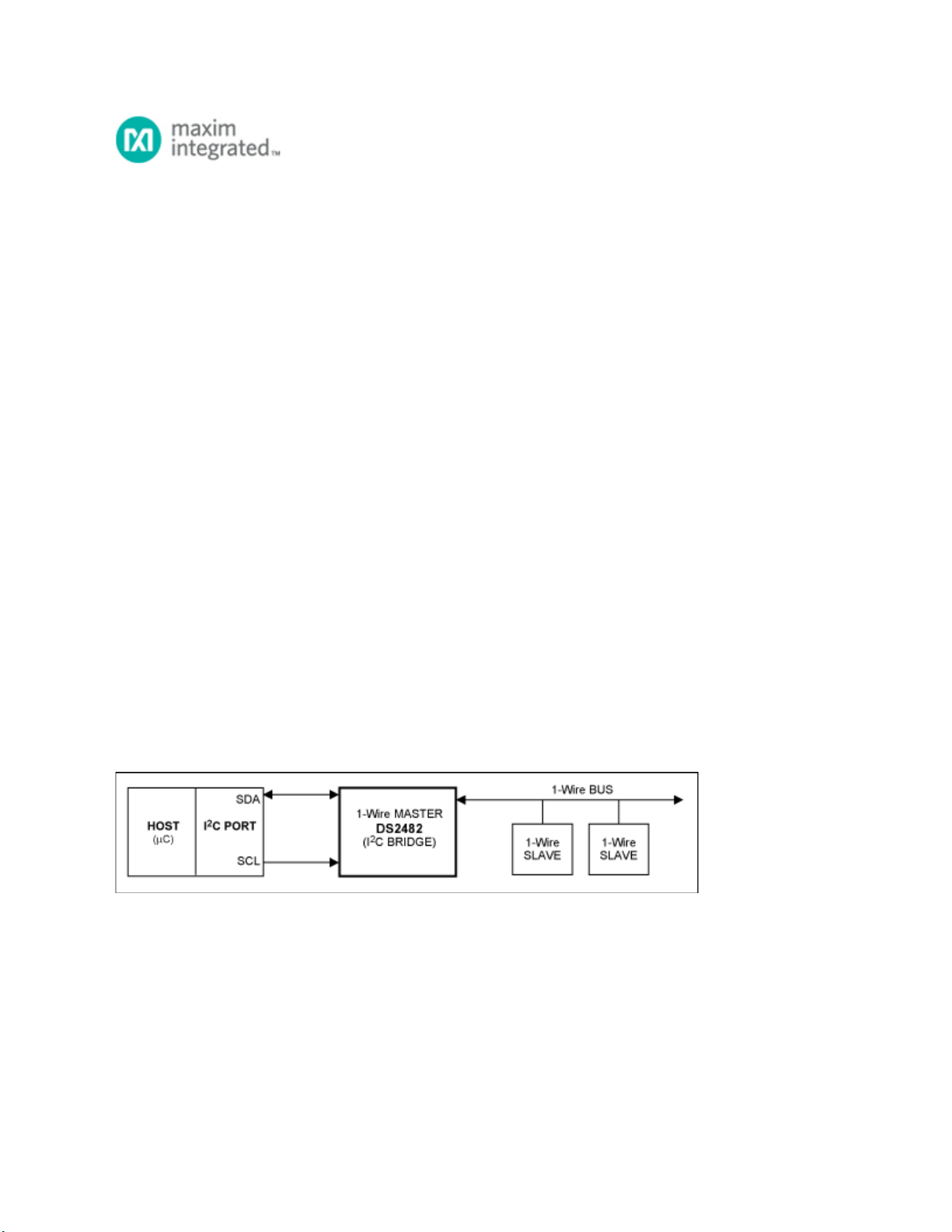
Figure 1 for a simplified diagram of the DS2482 configuration. This document presents an efficient
application programming interface (API) implementation of the basic and extended 1-Wire operations
using the DS2482. The I²C communication for each 1-Wire operation is explained. With the exception of
programming EPROM-based devices such as the DS250x series, these operations provide a complete
foundation to perform all the functions for current and future 1-Wire devices. Abstracting the 1-Wire
operations in this fashion leads to 1-Wire applications that are independent of the 1-Wire master type.
This document complements the DS2482 data sheets, but does not replace them. The DS2482 is
available in three configurations, a single-channel 1-Wire master (DS2482-100), a singe channel 1-Wire
master with low-power sleep mode (DS2482-101), and an eight-channel 1-Wire master (DS2482-800).
Figure 1. Simplified illustration of DS2482 function as a bridge for I²C communication and a 1-Wire
network.
The 1-Wire Interface
There are a few basic 1-Wire functions, called primitives, which an application must have to perform any
1-Wire communication session. The first function (OWReset) resets all the 1-Wire slaves on the network,
readying them for a command from the 1-Wire master. The second function (OWWriteBit) writes a bit
from the 1-Wire master to the slaves, and the third function (OWReadBit) reads a bit from the 1-Wire
slaves. Since the 1-Wire master must start all 1-Wire bit communication, a "read" is technically a "write"
Page 1 of 20