
下载

Maxim > Design Support > Technical Documents > Application Notes > T/E Carrier and Packetized > APP 3121
Keywords: SCT, LIU, framer, T1, E1, J1, single chip transceiver, t1 e1 j1, SCTs, line interface unit, LIUs, transceivers
APPLICATION NOTE 3121
Selecting a T1/E1/J1 Single-Chip Transceiver
Mar 24, 2004
Abstract: This article, originally published in the October 2003 issue of Electronic Products magazine, discusses how to
select a T1/E1/J1 single-chip transceiver (SCT).
Introduction
T and E Carrier networks have come a long way since the T Carrier's introduction in the 1960s. Today, the designer will
find many features that have been integrated into the T1/E1/J1 single-chip transceiver (SCT).
Due to the numerous functions a transceiver can incorporate, this article will highlight some of the important features
that designs require.
T, E, and J Carrier Networks
T1 at 1.544Mbps is the lowest rate of the T Carrier hierarchy for digital multiplexed transmission across the North
American Public Switched Telephone Network (PSTN). It was originally designed to transport digitized voice. T1 uses
pulse code modulation and time-division multiplexing to transport up to 24 channels of carrier grade voice, called DS0s.
Each DS0 or timeslot carries up to 64kbps of information.
E1 is a European digital transmission format that carries up to 32 channels of voice whose multiplexed clock rate is
2.048Mbps.
Today, not only voice can be transported over a T1 or E1 line, but data as well, or a combination of both. T1 and E1
lines are used extensively in applications such as cellular base stations, business access routers, and private branch
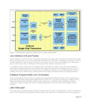
exchanges. Figure 1 shows a functional block diagram of a typical T1/E1/J1 SCT. Note: J1 is a variant of T1 that is
used exclusively in Japan.
Page 1 of 4