


下载

Maxim > Design Support > Technical Documents > Application Notes > Digital Potentiometers > APP 409
Maxim > Design Support > Technical Documents > Application Notes > General Engineering Topics > APP 409
Keywords: DS1267, digital potentiometers, digipot, digital pots, Xicor
APPLICATION NOTE 409
Using Multiple DS1267 Digital Potentiometers With
an 8051 Microprocessor Generating 3-Wire
Signals
Mar 29, 2001
Abstract: The DS1267 is a dual digital potentiometer with a serial "shift register" type interface. The shift
register has an input pin where data is shifted in as well as an output pin which shifts data out of the
last bit of the shift register when being written. This allows multiple DS1267s to be daisy-chained
together and programmed together on the same serial bus. The application note describes how to
accomplish this with circuit examples and pseudo code examples showing how to develop the code for
any microprocessor.
Introduction
Dallas Semiconductor's DS1267 Digital Potentiometers are ideal for systems requiring Digital to Analog
Converters (DAC), or systems that need a programmable bias current, voltage, or resistance without the
human intervention required by a traditional mechanical potentiometers. The DS1267 provides two digital
potentiometers in one package. A unique 3-wire protocol allows several of these chips to be placed in
series or in parallel. An optional stacked configuration allows the chip's two 8-bit potentiometers to be
placed in series, providing 9-bit accuracy. The DS1267 can be used in dual supply systems with an input
range between -5V and +5V as long as the substrate bias voltage is below the lowest input voltage used.
This application note provides an overview of different configurations for communicating to multiple
DS1267s with a common bus. It also provides the hardware and software required for communicating to
two DS1267s daisy-chained together in a series.
Hardware Setups for Communication with a DS1267
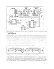
There are two primary ways that a 3-Wire bus can be connected to communicate with multiple chips. The
devices can either be connected in series, or in parallel. For either type of connection, 17 bit blocks of
data will be written to the part(s) at a time. The data will determine the position of the potentiometer
wipers and the stack output each time that the reset is de-asserted.
Series
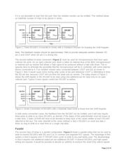
A standard series connection is shown in Figure 1 below. This method of connection works with
microprocessors that have bidirectional ports that are high impedance when expecting input. This allows
the feedback resistor to be used to drive the DQ pin from the COUT of the last device in the daisy chain.
Page 1 of 15