

下载
Application Report
SLVA505–February 2012
Understanding Motor Driver Current Ratings
Peter Millett ................................................................................................. Motor Drive Business Unit
ABSTRACT
There is much misunderstanding about the current ratings used with motor driver ICs, especially as
related to the selection of a motor driver part for a specific application. Complicating matters further is that
there is no standard way of specifying current ratings, so the exact meaning of the ratings can differ from
one vendor to another and in some cases even between different parts from the same vendor. This
application report explains the meaning of the different current ratings applied to motor driver parts and
specifically explains the ratings found in TI motor driver device datasheets.
Contents
1 Factors Limiting the Maximum Output Current of a Motor Driver ..................................................... 1
1.1 Thermal Limitations ................................................................................................ 1
1.2 Overcurrent Protection (OCP) Limitations ...................................................................... 2
1.3 Silicon and Package Limitations ................................................................................. 2
2 TI Motor Driver OCP Operation ........................................................................................... 3
3 TI Motor Driver Datasheet Ratings ....................................................................................... 4
3.1 Description .......................................................................................................... 4
3.2 Absolute Maximum Ratings ....................................................................................... 5
3.3 Recommended Operating Conditions ........................................................................... 5
3.4 Thermal Information ............................................................................................... 6
3.5 Electrical Characteristics .......................................................................................... 6
4 References ................................................................................................................... 7
List of Figures
1 Simplified OCP Schematic ................................................................................................ 3
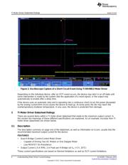
2 Oscilloscope Capture of a Short Circuit Event Using TI DRV8813 Motor Driver................................... 4
1 Factors Limiting the Maximum Output Current of a Motor Driver
The maximum drive current obtained from a given motor driver IC is limited by a number of factors. The
most restrictive of all these conditions limits the amount of current driven. This current level will depend
not only on the motor driver IC, but also the PCB construction, ambient temperature, and other factors.
1.1 Thermal Limitations
Even though a motor driver IC is thought of as a switch or set of switches, it is not a perfect switch. Power
is dissipated in the motor driver IC, primarily due to resistive losses which are proportional to drive current,
as well as from other sources such as internal quiescent power and switching losses.
The precise calculation of this power loss is complex and a subject of its own (refer to the application
report Calculating Motor Driver Power Dissipation, SLVA504). For the purposes of this discussion, we will
simplify the power loss to that which is dissipated in the FET ON-resistance of the power stage, called
R
DS(ON)
.
1
SLVA505–February 2012 Understanding Motor Driver Current Ratings
Submit Documentation Feedback
Copyright © 2012, Texas Instruments Incorporated