


下载

1
SLVA714A–June 2015–Revised May 2016
Submit Documentation Feedback
Copyright © 2015–2016, Texas Instruments Incorporated
Understanding IDRIVE and TDRIVE in TI Motor Gate Drivers
All trademarks are the property of their respective owners.
Application Report
SLVA714A–June 2015–Revised May 2016
Understanding IDRIVE and TDRIVE in
TI Motor Gate Drivers
NicholasOborny
ABSTRACT
The motor gate driver is an integrated circuit (IC) that primarily deals with enhancing external power
MOSFETs to drive an electric motor. The gate driver acts as an intermediate stage between the logic-level
control inputs and the power MOSFETs. The gate driver must be flexible enough to accommodate a wide
variety of external MOSFETs and external system conditions.
Texas Instrument’s IDRIVE and TDRIVE features provide an intelligent solution for driving the external
power MOSFETs. These features allow system designers to adjust the MOSFET slew rate, optimize
switching and EMI performance, reduce BOM count, and provide additional protection for the motor
system design.
This report describes the theory and methods behind enhancing a power MOSFET, how the IDRIVE and
TDRIVE features are implemented in TI motor gate drivers, and detail the system-level benefits.
Contents
1 Power MOSFET Theory and Operation .................................................................................. 3
1.1 Basics ................................................................................................................ 3
1.2 Parameters .......................................................................................................... 4
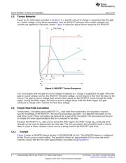
1.3 Turnon Behavior .................................................................................................... 6
1.4 Simple Slew-Rate Calculation..................................................................................... 6
1.5 Gate Drive Current.................................................................................................. 7
2 IDRIVE and TDRIVE ........................................................................................................ 8
2.1 IDRIVE Implementation............................................................................................ 8
2.2 TDRIVE Implementation.......................................................................................... 10
3 System Benefits ............................................................................................................ 14
3.1 Slew Rate Control................................................................................................. 14
3.2 BOM Reduction.................................................................................................... 16
3.3 System Protection................................................................................................. 17
3.4 EMI Optimization .................................................................................................. 17
List of Figures
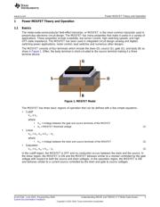
1 MOSFET Model.............................................................................................................. 3
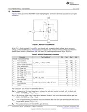
2 MOSFET Circuit Model ..................................................................................................... 4
3 MOSFET Gate-Charge Curve.............................................................................................. 5
4 MOSFET Turnon Response................................................................................................ 6
5 Measured MOSFET Slew Rate............................................................................................ 7
6 Switch IDRIVE Method...................................................................................................... 8
7 Multiple IDRIVE Settings.................................................................................................... 9
8 Current Source IDRIVE Method ........................................................................................... 9
9 Cross Conduction Example............................................................................................... 10
10 Dead Time Example ....................................................................................................... 11
11 V
GS
Monitor Example....................................................................................................... 11