下载

Mechanical Design Notes
www.vishay.com
Vishay Semiconductors
Rev. 1.6, 18-Feb-13
1
Document Number: 80075
THIS DOCUMENT IS SUBJECT TO CHANGE WITHOUT NOTICE. THE PRODUCTS DESCRIBED HEREIN AND THIS DOCUMENT
ARE SUBJECT TO SPECIFIC DISCLAIMERS, SET FORTH AT www.vishay.com/doc?91000
Mechanical Design Notes
There are many aspects in the design of an appliance, which
will affect the IR sensitivity of the receiver such as window
size, window material, distance of the receiver to the
window or to a light guide.
WINDOW
The size of the window in front of the IR receiver should be
large enough so that the viewing angle of the IR receiver is
not overly restricted. The window size and the distance of
the IR receiver behind the window should be designed to
enable a directivity of at least ± 50°. A module with a
mechanical holder (e.g. TSOP4838AY1) can sometimes help
to place the sensitive area of the IR receiver module closer
to the window.
When the front panel of an appliance is black, it is usually
desired that the optical window in front of the IR receiver
also be tinted black. That means that a plastic material is
required, which is transparent for infrared signals but
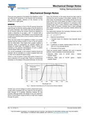
opaque for visible light. The diagram in figure 1 shows an
example of the spectral transmittance of such a plastic
material (Bayer Makrolon color 45/601).
The cut-off wavelength of the window material should be
between 700 nm and 850 nm in order to appear black and
in order not to absorb IR signal energy.
There is a loss of power in every front panel of about 8 %
due to reflection (4 % at each side). There is a compromise
necessary on the design of the panel thickness. On the one
hand, the thickness of the panel should be kept small to
minimize the loss of energy in the plastic material. On the
other hand, the thickness of the plastic should not be too
small (or the color of the plastic too light) in order to avoid
being able to see inside the appliance. In contrast to other
products that have a shiny external metal shielding, the
Vishay TSOP IR receiver modules have a black package
with internal shielding, which prevents visibility behind the
front panel.
The relationship between the necessary thickness and the
optical transmittance is given by:
()= (1 - ) x e
(-a() x d)
() = Spectral transmittance
=
Constant factor for reflection loss (typically about
0.08
)
e = 2.718282
() = Coefficient of plastic material (about 0.03 mm
-1
at
950 nm in the example above)
d = Thickness of front panel
There are several plastic materials with such a spectral
behavior. Some examples of polycarbonate are:
• Makrolon 2805; color #: 45-601 (blue - black);
supplier: Bayer
• Makrolon 2805: color #: 45-401 (green - black);
supplier: Bayer
Fig. 1 - Spectral Transmittance for IR Transmissive Window Material
Another very common design is a silver colored front panel,
usually either equipped with tiny holes for the IR signal to
pass through or a partially reflecting material for this
purpose. Although stylish, this design is very non-optimal in
terms of transmission range as there is a high loss of signal
through the panel.
0
10
20
30
40
50
60
70
80
90
100
400 500 600 700 800 900 1000 1100 1200
Wavelength (nm)
Spectral transmittance (%)
spectral transmittance
of tinted filter
spectral sensitivity of
TSOP IR receiver


