

下载
BLDC Motor Control Kit including
ATA6833/ATA6834 and ATmega32M1
Getting Started
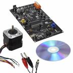
1. Kit Contents
• 1 BLDC Motor Application Board: ATA6833/ATA6834-DK1
• 1 Display Controller Board: ATA6833/ATA6834-DK2
• 1 Brushless DC Motor Ref: FL42BLS01-001 (3 Phases, 8 Poles, 12 VDC)
• 1 Getting Started Note
• 1 CD-ROM Atmel Products Technical Library
2. Prepare Connections
1. Connect the Motor Application Board X5 to the Display Controller Board X5.
2. Connect the motor as indicated in Table 2-1, motor phases (3 thick wires on pin 1 to
3) and Hall sensors (5 thin wires on pin 4 to 8).
3. Connect the Power Supply 12V to X1.
Table 2-1. BLDC Application Board Wires
Pin
Number
Signal Names on
PCB Bottom Function
Motor
Wire Remark Direction
1 Ph_A Motor Phase A Yellow Thick wire Output
2 Ph_B Motor Phase B Red Thick wire Output
3 Ph_C Motor Phase C Black Thick wire Output
4 5V Power 5V Red Thin wire Output
5 HALL_A Hall A Blue Thin wire Input
6 HALL_B Hall B Green Thin wire Input
7 HALL_C Hall C White Thin wire Input
8 GND Power GND Black Thin wire Output
ATA6833/
ATA6834-DK
Application Note
9153A–AUTO–12/08