


下载
Digital Isolators Can Be Used
in Intrinsic Safety Applications
Mark Cantrell
Analog Devices, Inc.
Designers of intrinsic safety
(
IS
)
equipment know the challenges of getting
signals in and out of your equipment. New technologies are available that
have tantalizing properties that would make a design smaller, simpler,
lower power, faster, or all four, but it is not clear if or how you can use
them because of the requirements of the IS safety standard.
Introduction
If you are new to the world of intrinsic safety
(
IS
)
, you might be a little
overwhelmed by the terminology and concepts. It tends to be a world
apart from the rest of electronic design and takes a while to come to
terms with the terms and world view
(
pun intended
)
. Let’s review the
primary concepts behind IS isolator components. It is all about safety
around flammable atmospheres and dust. The primary concept is that
the design cannot be capable of creating a spark or flame with the
energy available to it so that under every conceivable fault scenario, the
insulation will remain intact. All of the testing and design guidelines laid
out in IEC 60079-11 are really to achieve those two goals. The standard
approaches the safety side by mandating insulation properties such as
thickness or distance along the surface. While this is the common way
to approach insulation safety, the safety margins chosen were much more
conservative than is typical in IEC standards.
The world of intrinsic safety is divided into two zones: the intrinsically safe
zone where dust and gas create hazardous conditions, and the rest of the
world
(
the non-IS zone
)
. Within the IS zone, energy is limited, and voltages
tend to run in the 24 V to 60 V range with limited current and in the safety
extra low voltage
(
SELV
)
range. In this environment, a component must
be able to dissipate the maximum power that the system can provide it
without sparking or burning. This can be achieved a couple of ways. One
is to build rugged components that can dissipate a lot of power without
heating up. The other is to protect the inputs and outputs with discrete
components that will limit the power to what can be tolerated by the part.
Typically, the limiting components consists of a Zener diode to limit the
voltage and a fuse or resistor to limit the current. If you consider a modern
system with even a modest number of components, this can start to
become a large number of passive components surrounding every active
component. The non-IS zone, where you and I live, has line voltages in the
100 V to 250 V range with potentially unlimited current. To be called safe,
an isolating device must be able to survive a fault to the line power and
not invalidate its insulation or cause an arc spark or burn that gets into the
IS zone. That means very robust interfaces and protection devices capable
of handling a very energetic fault. Robust protection uses even more and
larger components and board space.
Did I mention that the IS standards committees are very conservative and
do not adopt new technologies quickly? The technology of choice to get
logic level communications between zones is the venerable optocoupler.
There has been a strained relationship between optocoupler manufactur-
ers and the conservative insulation requirements of the IS standard. The IS
standard does not assume much about the quality of a piece of insulation,
it only recognizes two types of insulation. The first is a casting compound
that can cover relatively reliable mold compounds for ICs, as well as pot-
ting compounds that are far less controlled. The second type of insulation
is everything else that is solid and insulates, which would encompass
everything from glass and thin polymer films to wax paper. The capabili-
ties of these insulation materials and the quality of their application may
vary widely. The standard takes the conservative approach and mandates
thick layers of insulation. When an optocoupler was designed with the
minimum thickness prescribed in the standard, it became difficult to make
a component that functioned with any kind of speed. Efforts were made
over the evolution of the standard to reduce the through-the-insulation
requirements, allowing better performing optocouplers to be used. New
testing was created, the optocoupler carbonization test, to verify that opto-
couplers would not rupture when the very high power available in the non-IS
zone was applied. The results were mixed at best and most designers and
optocoupler companies were not satisfied with the compromises.
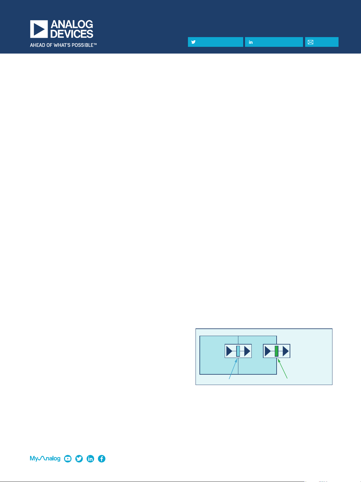
Figure 1. Isolation layout of an intrinsically safe system.
Non-IS Zone (The Real World)
IS Zone
V
ISO
= 500 V
PEAK
V
MAX
= 60 V
DC
P
MAX
= 1 W
IS Zone
V
ISO
= 500 V
PEAK
V
MAX
= 60 V
DC
P
MAX
= 1 W
V
ISO
= 4000 V
PEAK
V
MAX
= 60 V
DC
P
MAX
= Unlimited
IS-to-IS Isolator IS-to-Non-IS Isolator
Visit analog.com
|
Share on Twitter
|
Share on LinkedIn
|
Email
TECHNICAL ARTICLE