
下载
AN-915
APPLICATION NOTE
One Technology Way • P. O. Box 9106 • Norwood, MA 02062-9106, U.S.A. • Te l: 781.329.4700 • Fax: 781.461.3113 • www.analog.com
CDR Operation for ADF7020, ADF7020-1, ADF7021, and ADF7025
by Austin Harney and Philip Quinlan
Rev. 0 | Page 1 of 4
INTRODUCTION
The clock and data recovery (CDR) module in the ADF7020,
ADF7020-1, ADF7021, and ADF7025 devices is implemented
using an oversampled digital phased-locked loop (DPLL),
operating at 32× the transmit data rate. The CDR PLL
resynchronizes the received bit stream to a local bit clock,
Rx clock.
The phase detector in the DPLL measures the phase error by
comparing the time between bit transitions in the recovered bit
stream and the rising edge of a local bit clock. A numerically
controlled oscillator (NCO) generates the recovered clock.
When a bit transition is detected at the output of the post-
demodulator, the phase of the NCO output is adjusted by +1/32,
0, or −1/32 of a bit time.
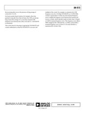
A simplified block diagram of the CDR is shown in
Figure 1.
F
S
= 32 F
DATA
Rx DATA
Rx CLOCK
DQ
PHASE
DETECTOR
LOOP
FILTER
NCO
POST-DEMOD
LPF
FSK
DEMOD
NOMINAL
COUNT = 32 F
DATA
06761-001
Figure 1. Block Diagram of Symbol Timing Recovery PLL
MAXIMIZING DATA RATE TOLERANCE
The data rate tolerance of the CDR is dependent on the number
of bit transitions in the transmit bit stream. This tolerance is
maximized, and the CDR lock time is minimized when a
maximum transition bit pattern, 10101010…, is used as a
preamble. A maximum NCO phase adjustment of 1/32 of a bit
period is permitted in a single bit period. This results in a
maximum data rate tolerance of 1/32 × 100 = ±3.13% with a
101010… preamble.
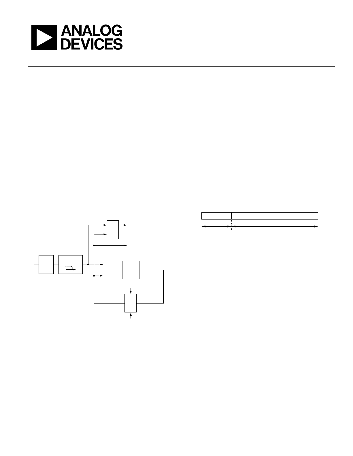
However, this data rate tolerance is reduced in the data field, as
shown in
Figure 2, where bit transitions are not guaranteed to
occur at regular intervals. In general, it is the run-length limit
(RLL) properties of the transmit data field that determine the
actual data rate tolerance of the CDR.
The RLL property of a code defines the maximum number
of identical contiguous bits in the encoded bit stream. In
general, all encoding schemes are defined by a (d, k) constraint,
where d, k represents the minimum and maximum number of
identical symbols between unequal symbols.
As an example, a code with a (d, k) equal to (0, 4), has no more
than four contiguous identical bits. Thus, in general, it is the
k constraint of the code used for data field encoding that deter-
mines the maximum data rate tolerance.
PREAMBLE
SYNC WORD/ADDRESS/DATA/CRC.......1010101010
DATA FIELD
0
6761-002
Figure 2. Typical Message Format
As an example, Manchester encoding has a maximum RLL of
2 bits, that is, the maximum number of contiguous bits in the
encoded Manchester sequence is 2 bits. For example, a
Manchester encoder input code word of 0101 results in an
output code word of 01100110 at twice the input data rate.
Thus, the maximum tolerance is ±3.125%/2 = ±1.56% of the
Manchester encoded output rate. In practice, however, the
tolerance is larger than this because the average RLL at the
Manchester encoder output is less than 2. Simulations show
that, given a random input binary bit sequence, it is possible
to support a data rate tolerance of approximately ±2% using
Manchester encoding.
Another low complexity encoding scheme that can be used to
maximize data rate tolerance is to insert additional data bits at
specific time intervals in the transmit bit stream to guarantee a
specific maximum RLL. This is referred to as a bit stuffing code.
The advantage to this scheme is that it is simple to implement,
and it does not suffer from the high code rate loss that exists
with Manchester encoding, where the code rate is 1/2.