


下载
AN-1451
APPLICATION NOTE
One Technology Way • P. O. Box 9106 • Norwood, MA 02062-9106, U.S.A. • Tel: 781.329.4700 • Fax: 781.461.3113 • www.analog.com
RS-485 Fail-Safe and Loss of Signal Detector for Energy Metering Applications
by Richard Anslow
Rev. 0 | Page 1 of 5
INTRODUCTION
Energy metering communication ports, which commonly use
RS-485 interfaces, can be subjected to large common-mode
noise, ground potential differences, and high voltage transients.
In particular, over long cable runs between the master node (the
central data collection point) and the energy meter slave, these
hazards can either corrupt data communication or even cause
permanent damage to the RS-485 interface.
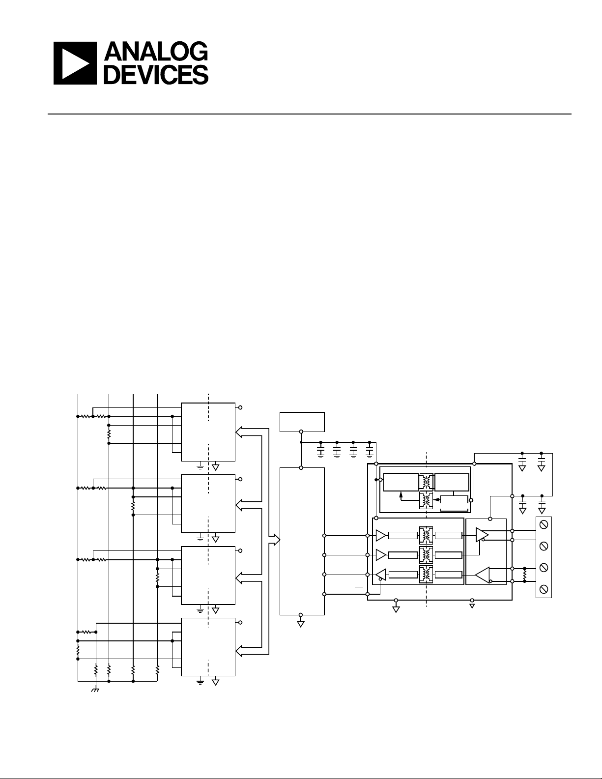
Figure 1 shows the possible isolation domains in a 3-phase energy
metering slave node. The isolation barrier can either be placed
at the analog front end (AFE) or at the RS-485 communications
port. Use the 3-phase AFE with the ADE7912 or ADE7913 to
isolate the communications interface and to measure voltage
and current on Phase A, Phase B, and Phase C. The RS-485
transceiver isolates the 3-phase slave node from the master node,
and allows reliable control and data transmission between the
master node and the energy meter slave node. Regardless of
where the isolation barrier is placed, Analog Devices, Inc.,
iCoupler® technology provides reliable operation in the
presence of system grounding differences, common-mode
noise, and voltage transients.
Higher level energy metering standards that use RS-485 as the
physical layer, such as IEC 62052-11 and IEC 62053-21
(alternating current static watt-hour meters for active energy
Class 1 and Class 2) specify a defined output state for when the
RS-485 receiver operates on an idle bus (no active signaling).
The ADM2682E iCoupler signal and isoPower® isolated RS-485
transceiver features a true fail-safe feature, offering a logic high
receiver output feature for bus idle, open circuit and short-circuit
conditions. Additional system diagnostics can be added to the
RS-485 node if a bus loss of signal (LOS) detector circuit is used.
NEUTRAL
PHASE
C
ISOLATION
BARRIER
LOAD
PHASE
A
EARTH
PHASE
B
SPI INTERFACE
PHASE A
ADE7912/
ADE7913
IP
IM
V1P
VM
V2P
GND
MCU
GND
ISO_A
3.3V
PHASE B
ADE7912/
ADE7913
IP
IM
V1P
VM
V2P
GND
MCU
GND
ISO_B
3.3V
PHASE C
ADE7912/
ADE7913
IP
IM
V1P
VM
V2P
GND
MCU
GND
ISO_C
3.3V
NEUTRAL
LINE
ADE7912/
ADE7913
(OPTIONAL)
IP
IM
V1P
VM
V2P
GND
MCU
GND
ISO_N
3.3V
SYSTEM
MICROCONTROLLER
ADM2682E/ADM2687E
TxD
A
B
Y
Z
DE
RxD
TRANSCEIVER
RE
GND
2
ENCODE
ENCODE
ENCODE
DECODE
DECODE
DECODE
OSCILLATOR
RECTIFIER
V
ISOOUT
V
CC
V
CC
V
ISOIN
R
T
3.3V POWER
SUPPLY
100nF
100nF 10µF
GND
MCU
GND
MCU
ISOLATION
BARRIER
10µF 100nF 10nF
REGULATOR
isoPOWER DC-TO-DC CONVERTER
DIGITAL ISOLATIONiCoupler
R
100nF 10µF
D
15551-001
Figure 1. Possible Isolation Domains for a 3-Phase Energy Metering Slave at the Isolated AFE or at the RS-485 Communications Port