

下载
AN-641
APPLICATION NOTE
One Technology Way • P.O. Box 9106 • Norwood, MA 02062-9106 • Tel: 781/329-4700 • Fax: 781/326-8703 • www.analog.com
INTRODUCTION
This application note describes a high accuracy, low cost
3-phase power meter based on the ADE7752. The meter
is designed for use in a Wye-connected 3-phase, 4-wire
distribution system. The ADE7752 may be designed into
3-phase meters for both 3-wire and 4-wire service. This refer-
ence design demonstrates the key features of an ADE7752
based meter, and is not intended for production.
The ADE7752 is a low cost single-chip solution for electrical
energy measurement that surpasses the IEC 61036 Class
1 meter accuracy requirement. It typically realizes less
than 0.1% error over a 500:1 current dynamic range for
balanced polyphase loads. The chip contains a reference
circuit, analog-to-digital converters, and all of the digital
signal processing necessary for the accurate measurement
of active energy. A differential output driver provides
direct drive capability for an electromechanical counter, or
impulse counter. A high frequency pulse output is provided
for calibration. An additional logic output on the ADE7752,
REVP, indicates negative active power on any phase or a
possible miswiring. The ADE7752 data sheet describes
the device’s functionality in detail and is referenced several
times in this document.
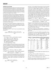
DESIGN GOALS
Specifi cations for this Class 1 meter design are in accordance
with the accuracy requirements of IEC 61036, and Indian
Standards IS 13779-99. Tables I and II review the overall
accuracy at unity power factor and at low power factor.
Table I shows the specifi cations of the meter for both bal-
anced loads and balanced lines. Table II addresses balanced
polyphase voltages with a single-phase load.
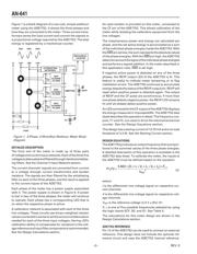
The meter was designed for an I
MAX
of 50 A/phase, an I
b
of
5 A/phase, and a 100 impulses/kWh meter constant. The
ADE7752 provides a high frequency output at the CF pin.
This output is used to speed the calibration process and
provide a means of quickly verifying meter functionality
and accuracy in a production environment. CF is 16 times
F1, F2, the frequency outputs. In this case, CF is calibrated
to 1600 impulses/kWh. The meter is calibrated by vary-
ing the attenuation of the line voltage using the resistor
networks on each phase. Each phase to neutral voltage is
240 V. See the Channel 2 Input Network section.
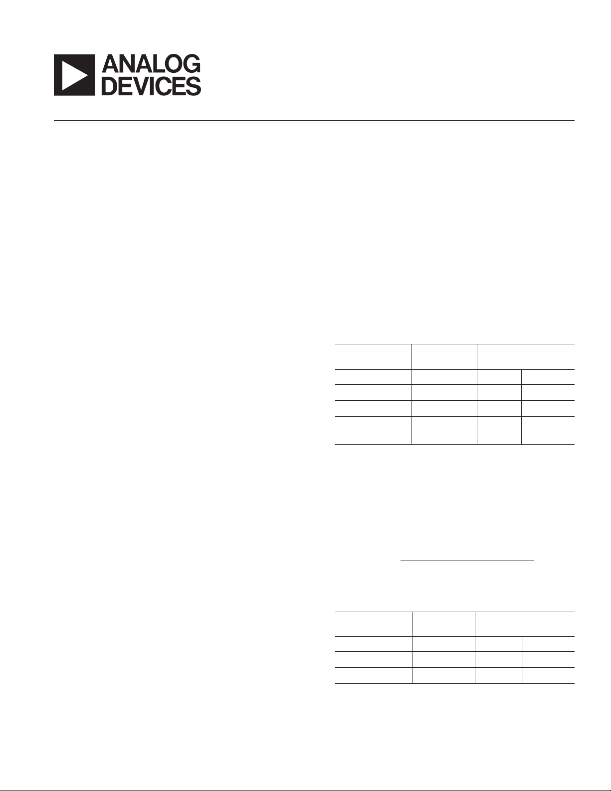
An additional specifi cation for this meter design is taken
from IS 13779-99. The specifi cation states that the meter
must work with only one phase active at 30% lower and
20% higher than the nominal line value.
Table I. Accuracy Requirements
(for a polyphase balanced load)
Percentage Error Limits
3
Current Value
1
PF
2
Accuracy
Class 1 Class 2
0.05 I
b
£ I < 0.1 I
b
1 ±1.5% ±2.5%
0.1 I
b
£ I < I
MAX
1 ±1.0% ±2.0%
0.1 I
b
£ I < 0.2 I
b
0.5 inductive
±1.5% ±2.5%
0.8 capacitive ±1.5%
NOTES
1
The current ranges for specifi ed accuracy shown in Table I are expressed
in accordance with IEC 61036, Table 15 percentage error limits, Sec-
tion 4.6.1, p. 53.
2
Power factor (PF) in Table I relates to the phase relationship between the
fundamental voltage and current waveforms. In this case, PF can be
defi ned as PF = cos(), where is the phase angle between pure sinusoidal
current and voltage.
3
Accuracy is defi ned as the limits of the permissible percentage error. The
percentage error is defi ned as:
Percentage Error
energy registered by meter –true energy
100%
true energy
=×
(1)
Table II. Accuracy Requirements
*
(for a polyphase meter with single-phase load)
Percentage Error Limits
Current Value PF
Accuracy
Class 1 Class 2
0.1 I
b
£ I < I
MAX
1 ±2.0% ±3.0%
0.2 I
b
£ I < I
MAX
0.5 inductive
±2.0% ±3.0%
*
Accuracy class for unbalanced load as defi ned in IEC 61036, Table 13,
Section 4.6.1, p. 53, Edition 2.1.
A 3-Phase Power Meter Based on the ADE7752
By Stephen English and Rachel Kaplan
REV. 0