


下载
AN-923
APPLICATION NOTE
One Technology Way • P. O. Box 9106 • Norwood, MA 02062-9106, U.S.A. • Te l: 781.329.4700 • Fax: 781.461.3113 • www.analog.com
Designing a System Using the ADAU1701/ADAU1702 in Self-Boot Mode
by Jerad Lewis
Rev. 0 | Page 1 of 4
INTRODUCTION
The ADAU1701/ADAU1702 can be used in a system without a
microcontroller by using the self-boot feature. This allows the
ADAU1701/ADAU1702 to boot itself as an I
2
C master from an
external EEPROM at power-up or reset. In the absence of a micro-
controller, real-time control of the DSP is achieved by using the
multipurpose pins with buttons, switches, potentiometers, or other
control devices. When designing a self-booting system with these
ICs, some consideration must be taken for in-system programming
and tuning from the SigmaStudio™ graphical programming tool.
HARDWARE SETUP
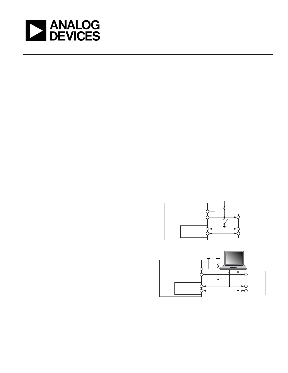
The circuit in Figure 3 shows the ADAU1701/ADAU1702 set
up in self-boot mode in an application circuit connected to an
EEPROM. The maximum necessary memory size for the
program, parameters, and interface registers of the ADAU1701
is 9248 bytes, or just over 8.5 kB. The ADAU1702 can use a
maximum of 6688 bytes for its program, parameters, and
interface registers. These numbers do not include register
settings or overhead bytes, but such factors do not add a
significant number of bytes. In addition, this much memory is
only needed if the program RAM (1024 × five bytes), parameter
RAM (1024 × four bytes), and interface registers (8 × four bytes)
are completely full. Most applications do not use the full program
and parameter RAMs; therefore, 8 kB EEPROM is sufficient.
The ADAU1701/ADAU1702 reads from EEPROM Chip
Address 0xA1. The LSBs of the addresses of some EEPROMs
are pin configurable; in most cases, these pins should be tied
low to set this address.
A self-boot operation is triggered on the rising edge of
RESET
when the SELFBOOT and WP pins are set high. The ADAU1701
reads the program, parameters, and register settings from the
EEPROM. After the ADAU1701/ADAU1702 finishes self-
booting, additional messages can be sent to the ADAU1701/
ADAU1702 on the I
2
C bus, although this typically is not
necessary in a self-booting application. In self-booting mode,
the I
2
C device address is 0x68 for a write and 0x69 for a read.
The ADDRx pins have different functions when the chip is in
this mode; therefore, these pins’ settings are ignored.
The ADAU1701/ADAU1702 does not self-boot if WP is set low.
Holding this pin low allows the EEPROM to be programmed
in-circuit. The WP pin is pulled low (it typically has a resistor
pull-up) to enable writes to the EEPROM, but this in turn
disables the self-boot function until the WP pin is returned
high. When the application circuit is in operation, as it will be
in the final product, the WP pin should be pulled high, as
shown in
Figure 1.To program the ADAU1701/ADAU1702 and
burn the EEPROM, the WP signal should be set low when
SigmaStudio is connected to the I
2
C bus through the USB
adapter board. The PC-connected setup is illustrated in
Figure 2.
When designing an application schematic, a jumper header
should be put on the WP trace so that it can be easily tied to
ground, and a 3-pin (SDA, SCL, GND) header should be
connected to the I
2
C port for the programming connection.
ADAU1701/
ADAU1702
SELFBOOT
I
2
C
CONTROL
PORT
SDA
SCL
WP
SDA
EEPROM
3.3V 3.3V
SCL
WP
06819-001
Figure 1. ADAU1701/ADAU1702 Self-Boot Application Circuit
ADAU1701/
ADAU1702
SELFBOOT
SDA
SCL
WP
3.3V 3.3V
SDA
EEPROM
SCL
WP
06819-002
I
2
C
CONTROL
PORT
Figure 2. ADAU1701/ADAU1702 Self-Boot Circuit with PC Connected