


下载

26184.28B
A3982
DMOS Stepper Motor Driver with Translator
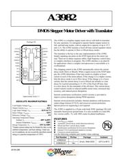
The A3982 is a complete stepper motor driver with built-in translator
for easy operation. It is designed to operate bipolar stepper motors in
full- and half-step modes, with an output drive capacity of up to 35 V
and ±2 A. The A3982 includes a fixed off-time current regulator which
has the ability to operate in Slow or Mixed decay modes.
The translator is the key to the easy implementation of the A3982.
Simply inputting one pulse on the STEP input drives the motor one
step. There are no phase sequence tables, high frequency control lines,
or complex interfaces to program. The A3982 interface is an ideal fit
for applications where a complex microprocessor is unavailable or is
overburdened.
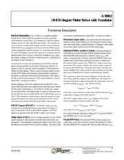
The chopping control in the A3982 automatically selects the current
decay mode (Slow or Mixed). When a signal occurs at the STEP input
pin, the A3982 determines if that step results in a higher or lower
current in each of the motor phases. If the change is to a higher current,
then the decay mode is set to Slow decay. If the change is to a lower
current, then the current decay is set to Mixed (set initially to a fast
decay for a period amounting to 31.25% of the fixed off-time, then
to a slow decay for the remainder of the off-time). This current decay
control scheme results in reduced audible motor noise, increased step
accuracy, and reduced power dissipation.
Internal synchronous rectification control circuitry is provided to
improve power dissipation during PWM operation.
Internal circuit protection includes: thermal shutdown with hysteresis,
undervoltage lockout (UVLO), and crossover-current protection.
Special power-on sequencing is not required.
The A3982 is supplied in a 24-pin wide-body SOIC (package LB) with
internally-fused power ground leads. It is also available in a lead (Pb)
free version (suffix –T), with 100% matte tin plated leadframes.
Low R
DS(ON)
outputs
Automatic current decay mode detection/selection
Mixed and Slow current decay modes
Synchronous rectification for low power dissipation
Internal UVLO and thermal shutdown circuitry
Crossover-current protection
Use the following complete part number when ordering:
AB SO LUTE MAX I MUM RAT INGS
Part Number Pb-free Package Ambient
A3982SLB –
24-pin, Wide SOIC –20°C to 85°C
A3982SLB-T Yes
Load Supply Voltage,V
BB
...................................35 V
Output Current, I
OUT
......................................... ±2 A
*
Logic Input Voltage, V
IN
..................... –0.3 V to 7 V
Sense Voltage, V
SENSE
.......................................0.5 V
Reference Voltage, V
REF
………..........................4 V
Operating Temperature Range
Ambient, T
A
................................. –20°C to 85°C
Junction Temperature, T
J(MAX)
.....................150°C
Storage Temperature, T
S
.................... –55°C to 150°C
*
Output current rating may be limited by duty cycle,
ambient temperature, and heat sinking. Under any
set of conditions, do not exceed the specified current
rating or a junction temperature of 150°C.
Package LB
FEATURES
24
23
22
21
20
19
18
17
16
15
14
13
1
2
3
4
5
6
7
8
9
10
11
12
Translator
OUT2A
SENSE2
VBB2
OUT2B
ENABLE
PGND
PGND
CP1
CP2
VCP
VREG
MS1
Charge
Pump
Reg
OSC
& Control Logic
OUT1A
SENSE1
VBB1
OUT1B
DIR
RESET
PGND
PGND
REF
STEP
VDD
ROSC
Approximate Scale 1:1