

Application Specification
©2012 Tyco Electronics Corporation, a TE Connectivity Ltd. company
All Rights Reserved
*Trademark
TE Connectivity, TE connectivity (logo), and TE (logo) are trademarks. Other logos, product and/or company names may be trademarks of their respective owners.
1 of 12
TOOLING ASSISTANCE CENTER
1-800-722-1111
PRODUCT INFORMATION
1-800-522-6752
This controlled document is subject to change.
For latest revision and Regional Customer Service,
visit our website at www.te.com
114-2036
FASTON* Straight Receptacles
with “F-” Crimp Feature
17 AUG 12 Rev F
All numerical values are in metric units [with U.S. customary units in brackets]. Dimensions are in millimeters [and inches].
Unless otherwise specified, dimensions have a tolerance of ±0.13 mm [±.005 in.] and angles have a tolerance of ±2°.
Figures and illustrations are for identification only and are not drawn to scale.
1. INTRODUCTION
This specification covers the requirements for application of FASTON Straight Receptacles with the “F”-Crimp
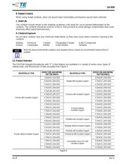
wire barrel feature. Receptacles are available in a variety of mating configurations, and in five series sizes: .312,
.250, .205, .187, and .110. The series designates the width of the mating tab. Also, depending on series and
mating end, receptacles are offered in many standard tab thicknesses.
When corresponding with TE Connectivity Personnel, use the terminology provided in this specification to
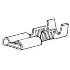
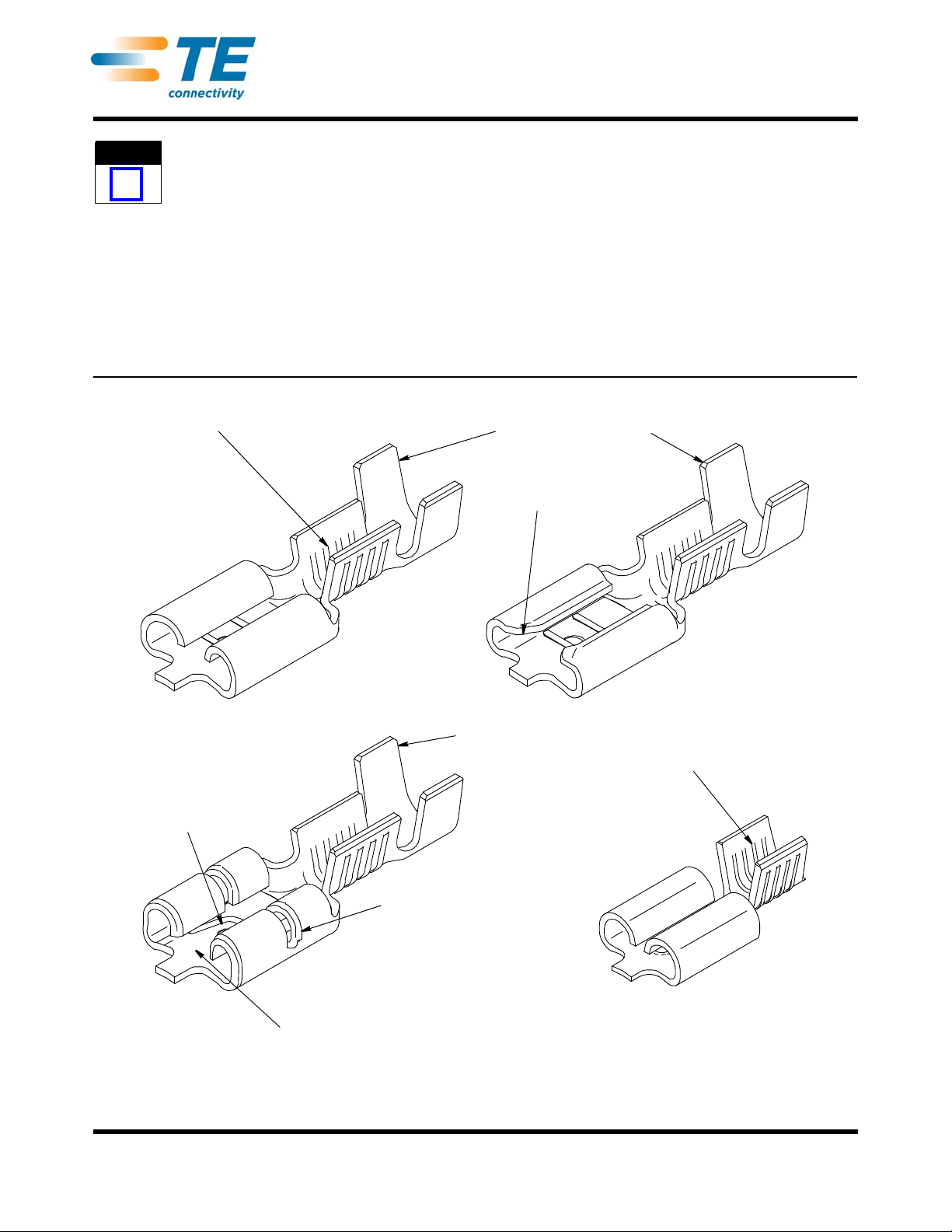
facilitate your inquiries for information. Basic terms and features of this product are provided in Figure 1.
Figure 1
NOTE
i
Serrated Wire Barrel
Insulation Support Barrel
Large Flared Lead-In
Insulation Support Barrel
Split-Roll Feature
Serrated Wire Barrel
Mating Tab Retention
Feature (Detent)
Cantilevered Dual-Slotted
Floor Design
Receptacles without
Insulation Support
Premier with
Insulation Support
Economy with
Insulation Support
Low Insertion Force (LIF)
with Insulation Support