

下载

Application Specification
FASTON* 110, 187, 205, 250, and 312
Series Tab Contacts for Printed
114--2115
LOC B
1 of 14
E2011 Tyco Electronics Corporation, a TE Connectivity Ltd. Company
All Rights Reserved
*Trademark
TE Connectivity, TE connectivity (logo), and TE (logo) are trademarks. Other logos, product and/or Company names may be trademarks of their respective owners.
TOOLING ASSISTANCE CENTER 1- -800- - 722 - - 1111
PRODUCT INFORMATION 1--800--522--6752
This controlled document is subject to change.
For latest revision and Regional Customer Service,
visit our website at www.te.com
Circuit (PC) Board Applications
20 APR 11 Rev E
All numerical values are in metric units [with U.S. customary units in brackets]. Dimensions are in millimeters [and
inches]. Unless otherwise specified, dimensions have a tolerance of +
0.13 [+.005] and angles have a tolerance of +2_.
Figures and illustrations are for identification only and are not drawn to scale.
1. INTRODUCTION
This specification covers the application of F ASTON 110, 187, 205, 250, and 312 Series Tab Contacts for
printed circuit (pc) board applications. The series designator is the width of the tab in hundredths of an inch.
There are loose piece contacts for hand tool application and continuous strip contacts for automatic machine
application.
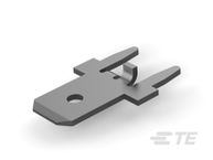
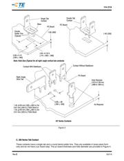
Each tab has a tapered lead--in to ease insertion of mating receptacle contacts, a dimple or hole that helps
retain the mating receptacle, and receptacle stops to prevent overinsertion of the mating receptacle contact.
The pc board contacts are available with a variety of solder tines. Those with round barrel and double solder
tines provide strength and stability for frequent connect/disconnect applications.
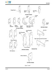
When corresponding with TE Connectivity Personnel, use the terminology provided on this specification to help
facilitate your inquiry for information. Basic terms and features of the contacts are provided in Figure 1.
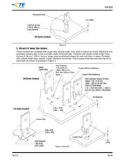
Figure 1 (cont’d)
Carrier Strip
Tab W idth
(Series Designator)
Stabilizer
Strip Form
Hole
Detent
Dimple Detent
Without Stabilizer
Extended Contact Tab
(In--Line Tab)
Solder
Tine
Double Tab Contact
(Right--Angle Vertical Tab)
Single Tab
Receptacle Stop
PC Board Stop
Contact Features
Receptacle
Stop
Carrier
Strip
Carrier
Strip
Extended Tab
(Right--Angle Horizontal Tab)
Contact Base
Loose Piece Form
Tapered Lead--In
NOTE
i