
122
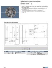
Speed setting via multi-option
control input
– Customer can operate input either with PWM signal, analogue voltage, external temperature
control module or resistor.
– The control signal-speed characteristics of the fan differ from the standard curve of the A
and P inputs (see p. 121).
– To attain the maximum speed, the control wire must be switched against UB.
– The control input is usually combined with an open collector tachometer (Type /2,
see page 110).
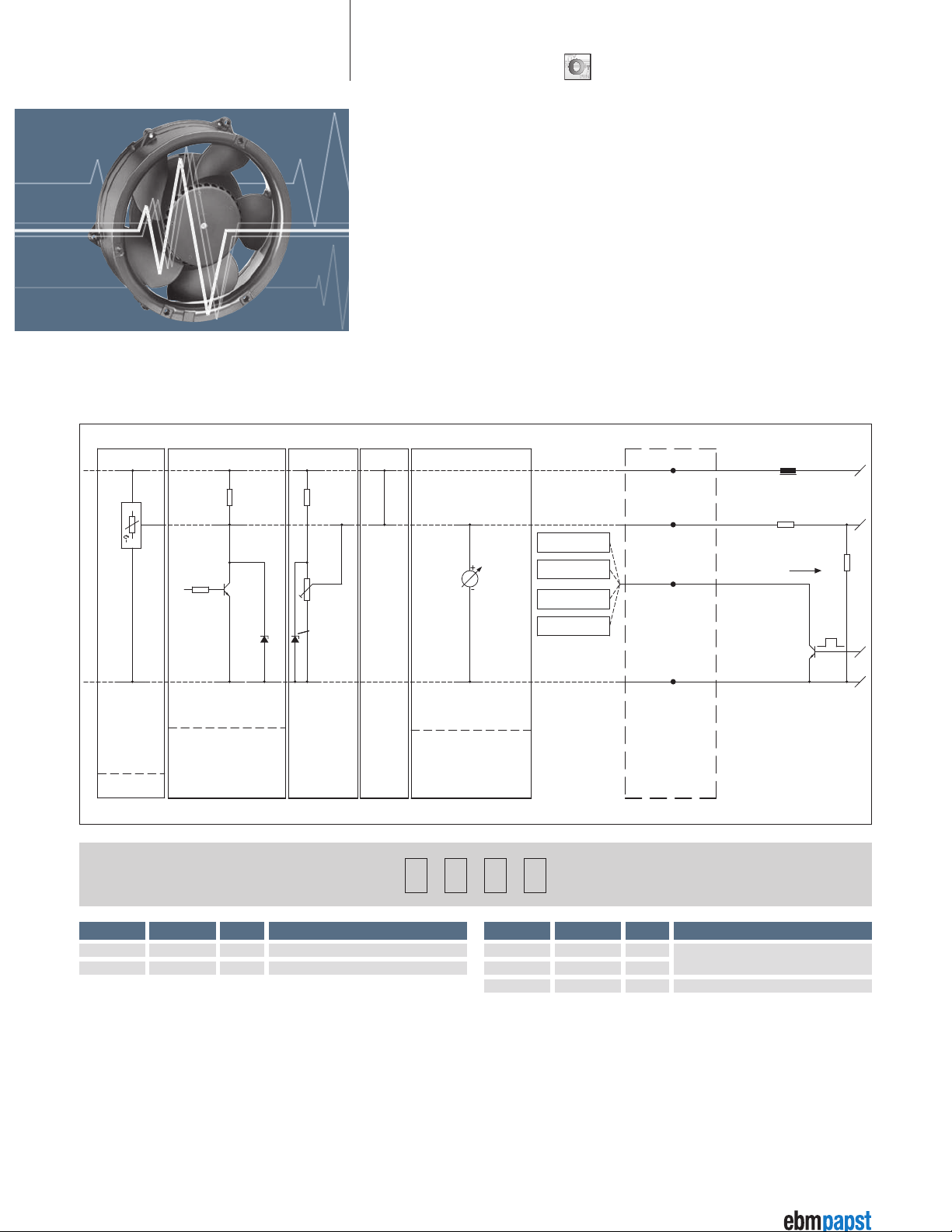
Speed setting via multi-option control input
PWM
U
violet
Temperature
control module
50002-1-0174
50003-1-0174
Speed setting
PWM 1 - 10 kHz
Speed setting
with
potentiometer
Full speed
100% PWM -> n=max
approx. 10% PWM -> n =min
< 10% PWM -> n= 0
start up at > 14 %
Speed setting
1 V - 10 V
10 V -> n=max
approx. 1 V -> n =min
< 1 V -> n= 0
start up at > 1.4 V
33 K 4.7 K
10 K
PWM
12 V 12 V
Speed display
Alarm
Controller
Counter
red
white
blue
Maximum ripple
± 3.5%
Tach output
pulses per revolution
GND
I
sink
max. 10 mA
Customer circuit
Notes on various control possibilities and their applications
Connection Fan
Lin/PWM control input
0-10 VDC / PWM
1 Tach white
0-10 V / PWM violet
Control input (Impedance 100 kΩ)
Tach output:
3 pulses / revolution
+
0-10 V
PWM
Tach
GND
Line Connection Colour Assignment / function Line Connection Colour Assignment / function
1 + red Maximum ripple ± 3.5 %
GND blue GND
Line 1
red violetwhiteblue