
下载
Application Specification
©2012 Tyco Electronics Corporation, a TE Connectivity Ltd. Company
All Rights Reserved
*Trademark
TE Connectivity, TE connectivity (logo), and TE (logo) are trademarks. Other logos, product and/or Company names may be trademarks of their respective owners.
1 of 4
TOOLING ASSISTANCE CENTER
1-800-722-1111
PRODUCT INFORMATION
1-800-522-6752
This controlled document is subject to change.
For latest revision and Regional Customer Service,
visit our website at www.te.com
LOC B
114-10026
Type II Screw Machine
Pin and Socket Contacts
27 SEP 12 Rev B
All numerical values are in metric units [with U.S. customary units in brackets]. Dimensions are in millimeters [and inches].
Unless otherwise specified, dimensions have a tolerance of ±0.13 [±.005] and angles have a tolerance of ±2°. Figures
and illustrations are for identification only and are not drawn to scale.
1. INTRODUCTION
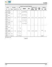
This specification covers the requirements for application of TE Connectivity Type II Screw Machine Pin and
Socket Contacts. These requirements are applicable to hand or automatic machine crimping tools. For specific
wire and insulation ranges relative to the products covered in this specification, see Figures 2 and 3.
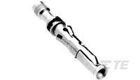
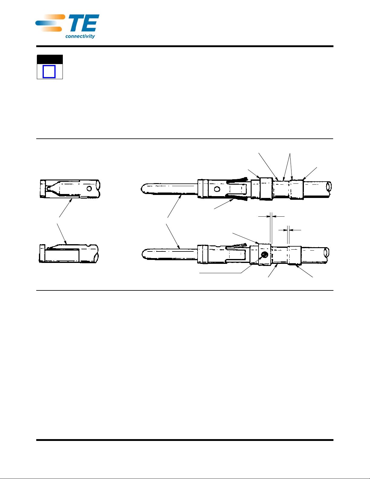
When corresponding with TE Personnel, use the terminology provided in this specification to facilitate your
inquiries for information. Basic terms and features of this product are provided in Figure 1.
Figure 1
2. REFERENCE MATERIAL
2.1. Revision Summary
• Updated document to corporate requirements
• Corrected information to table in Figure 2
2.2. Customer Assistance
Reference Product Part Numbers 201625 and 201627 and Product Code 5021 are representative of Type II Pin
and Socket Contacts. Use of these numbers will identify the product line and expedite your inquiries through a
service network established to help you obtain product and tooling information. Such information can be
obtained through a local TE Representative or, after purchase, by calling PRODUCT INFORMATION at the
number at the bottom of this page.
2.3. Drawings
Customer Drawings for product part numbers are available from the service network. If there is a conflict
between the information contained in the Customer Drawings and this specification or with any other technical
documentation supplied, call PRODUCT INFORMATION at the number at the bottom of this page.
NOTE
i
Wire Barrel
Color Matches Color on Die
Holding Screw and Tool Handles
Color Indicates Wire Range
Insulation Barrel
Wire Barrel Flash
Insulation Barrel Flash
Sight Inspection Hole
Socket
Pin
Locking Lance
Front Shoulder
Front
Bellmouth
Rear
Bellmouth